|
| |
TRUCK SERVICE MANUAL
TM 5-4210-230-14&P-1
ELECTRICAL
2.
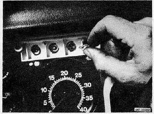
Grasp bulb and pull straight outward to remove plug-
in type bulb from socket (Figure 12).
In some cases it may be necessary to remove socket
from instrument cluster to remove bulb. See "Cluster
Illumination Lights" below.
Fig. 12 Removing Bulb from Face of Cluster
3.
Insert new bulb into socket.
4.
Install instrument cluster cover and screws.
5.
Check light operation.
Cluster Illumination Lights:
(K, Figure 11)
1.
Reaching up in front of instrument cluster, grasp light
socket.
2.
Turn bulb socket about one-eighth turn clockwise (as
viewed from front of vehicle). Pull socket (with bulb)
from instrument cluster (Figure 13).
Fig. 13 Removing Bulb and Bulb Socket from Cluster
3.
Grasp bulb and pull straight out to remove bulb from
socket.
4.
Install new bulb in socket.
5.
Position socket (with bulb) into instrument cluster
and turn socket one-eighth turn counterclockwise (as
viewed from front of vehicle) to secure.
6.
Check light operation.
DOME LIGHT
BULB REPLACEMENT
(Refer to Figure 14).
1.
Pry edge of lens inward to disengage retaining clips.
Remove lens.
2.
Disengage bulb from terminals.
3.
Position new bulb in terminals.
4.
Position lens in light assembly and engage retaining
clips.
5.
Check light operation.
Fig. 14 Dome Light
LIGHT ASSEMBLY REPLACEMENT
1.
Pry edge of lens inward to disengage retaining clips.
Remove lens.
2.
Remove light mounting screws.
3.
Pull light assembly away from cab panel to ,expose
wiring cable connector.
4.
Disconnect
wiring
cable
from
light
assembly.
Remove light assembly.
CTS-2781S Page 8
PRINTED IN UNITED STATES OF AMERICA
|