|
| |
TRUCK SERVICE MANUAL
TM 5-4210-230-14&P-1
ELECTRICAL
8.
If necessary, position sealed beam unit in headlight
mounting ring and secure with retaining ring and
screws.
9.
Connect three-way wiring connector to rear of sealed
beam unit.
10.
Engage mounting slots in headlight mounting ring
into collar grooves of adjustment screws. Connect
headlight retaining spring to headlight mounting ring.
11.
Install headlight bezel and secure with screws.
CAUTION
DO NOT overtighten bezel retaining screws. Overtightening
could cause damage (stripping) of threads in hood (fender).
12.
Check light operation.
13.
Check headlight aim. (See HEADLIGHT AIMING).
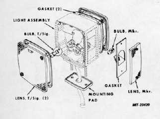
FRONT TURN SIGNAL/MARKER LIGHTS
BULB REPLACEMENT
Procedure applies to either turn signal or side marker bulbs.
Refer to Figure 9.
1. Remove lens mounting screws and remove lens.
2. Press bulb inward and turn counterclockwise to remove
bulb from socket.
3. Inspect bulb socket. If rusty or corroded, replace place
light assembly. Inspect lens gasket and replace if damaged.
4. Insert new bulb in socket, press inward and turn clockwise
to lock in place.
5. Position lens and gasket on light body and install lens
mounting screws.
6. Check light operation.
Fig. 9 Front Turn Signal/Marker Light
LIGHT ASSEMBLY REPLACEMENT
1.
Disconnect wiring cable from base of light assembly.
2.
Remove nuts, washers and wiring cable clip (where
used) from light mounting studs. Remove nuts and
washers
from
light
guard
mounting
bolts
(if
equipped).
3.
Remove light assembly (and light guard) from
fender.
4.
Inspect light mounting pad and replace if damaged or
deteriorated.
5.
Position mounting pad, light assembly (and light
guard) on fender.
6.
Install washers and nuts (and cable clip, where used)
on light mounting studs. Install light guard mounting
bolts, washers and nuts (if equipped).
7.
Plug wiring cable connector into light assembly.
8.
Tighten light (and light guard) mounting nuts.
9.
Check light operation.
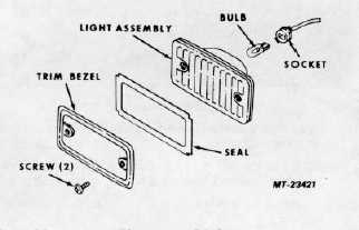
CLEARANCE AND IDENTIFICATION LIGHTS (CAB)
BULB OR LIGHT ASSEMBLY REPLACEMENT
(Refer to Figure 10).
1.
Remove light mounting screws. Remove trim bezel
and seal (where used).
2.
Pry light assembly from mounting recess in cab.
3.
Turn
bulb
socket
about
one-eighth
turn
counterclockwise and remove socket (with bulb) from
light assembly.
Fig. 10 Clearance Light
CTS-2781S Page 6
PRINTED IN UNITED STATES OF AMERICA
|