|
| |
ENGINE DIVISION SERVICE MANUAL
TM 5-4210-230-14&P-1
Clean cable terminals and apply a light coat of
lubricant/sealer (IH part number 472141-C1) of terminals at
assembly. Make sure cables seat properly on distributor cap
and spark plug terminals and in coil tower terminal.
Be sure ignition cables are routed correctly. Proper
routing of cables must be maintained to prevent crossfire.
PRIMARY VOLTAGE DROP TEST
This test can be used to help locate any high
resistance or loose connections in primary feed circuit
between the battery and the ignition coil positive (+) terminal.
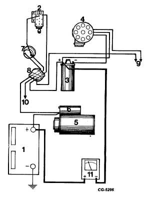
Test Procedure (Refer to Figure 58)
1.
Remove distributor cap, rotor and shield. "Bump"
starter to position sensor coil between two trigger
wheel teeth.
2.
Connect voltmeter positive (red) lead to battery
positive (+) terminal. Connect voltmeter negative
(black) lead to coil positive (+) terminal.
3.
Turn ignition switch "on" and observe voltmeter. A
reading of less than 1 volt should be obtained.
4.
Check circuit conditions by observing voltmeter while
flexing (moving) the connectors at the following
locations:
a.
Battery cables.
b.
Starter solenoid battery terminal.
c.
Dash panel (bulkhead) connector (where
used).
d.
Ammeter terminals.
e.
Ignition switch connections.
If fluctuation or an upswing of the voltmeter needle is
observed while flexing the connectors, a poor connection
exists and must be corrected.
Fig. 58 Primary Voltage Drop Test
1. Battery
7. Ammeter
2. Ignition Switch
8. Bulkhead Connector
3. Ignition Coil
9. To DTM
4. Distributor
10. To Alternator
5. Starter
11. Voltmeter
6. Solenoid
CGES-145-U Page 28
PRINTED IN UNITED STATES OF AMERICA
|