|
| |
ENGINE DIVISION SERVICE MANUAL
TM 5-4210-230-14&P-1
10.
Check Dwell.
Connect dwell meter to engine. Operate engine and
observe dwell reading. If necessary, re-adjust trigger
wheel-to-sensor air gap to obtain specified dwell.
11.
Check Timing.
Connect timing light to engine. Operate engine at
idle speed (distributor vacuum hose disconnected)
and check timing. Adjust timing if necessary.
SECONDARY CIRUCIT INSPECTION
Secondary
(high
voltage)
system
components
(distributor cap, rotor, coil, high tension cables and spark
plugs) should be checked as possible sources of trouble
before condemning the electronic units.
Distributor Cap and Rotor
Inspect distributor cap and rotor for cracks, carbon
tracking, loose terminals, dirt and contamination. Clean or
replace as needed.
Check rotor blade and spring for tightness. Check fit
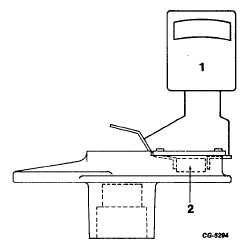
of rotor on distributor shaft. Check resistance type rotor with
ohmmeter. (Figure 56). If resistance exceeds 6000 ohms,
replace rotor.
Fig. 56 Rotor Resistance Test
1. Ohms X1000 Meter
2. Resistor
Coil
Inspect coil tower for cracks or carbon tracking.
Inspect primary terminals for corrosion and/or looseness.
Replace coil if any of these conditions are found.
Test resistance of coil primary and secondary circuits
with an ohmmeter (See Figure 57).
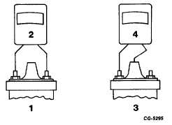
COIL RESISTANCE TESTS
Fig. 57 Coil Resistance Tests
1. Primary Circuit
3. Secondary Circuit
2. Ohms X1
4. Ohms X1000
If coil resistance tests are made with coil mounted in
vehicle, coil must be electrically isolated from the vehicle's
electrical system by disconnecting primary leads from coil
terminals and removing secondary cable from coil tower.
Set ohmmeter in OHM x 1 position. Connect
ohmmeter between coil primary terminals. Reading should be
between 1.2 and 1.4 ohms at 21 degrees C (70 degrees F).
Set ohmmeter in OHM x 1000 position. Connect
ohmmeter between one coil primary terminal and the coil
tower terminal. Reading should be within 9,000 to 12,000
ohms at 21 degrees C (70 degrees F).
If coil fails either resistance test, replace it.
High Tension Cables
Inspect secondary (high tension) ignition cables for
deterioration, carbon tracking at terminal boots and high
voltage leakage, especially at cable support brackets.
Test resistance of cables with an ohmmeter.
Resistance should not exceed 30,000 ohms on cables up to
914 mm (36") long or 45,000 ohms on cables over 914 mm
(36") long.
Check sealing and insulating qualities, of distributor
cap, coil tower and spark plug boots. Replace if needed.
CGES-145-U Page 27
PRINTED IN UNITED STATES OF AMERICA
|