|
| |
ENGINE DIVISION SERVICE MANUAL
TM 5-4210-230-14&P-1
C.
If voltage is 0 to 5 volts:
Disconnect voltmeter. Remove brown wire from coil
negative (-) terminal. Reconnect voltmeter between
coil negative (-) terminal and ground (Figure 53).
With ignition switch "on", observe voltmeter. If
voltage reading is still 0 to 5 volts, coil is faulty and
must be replaced.
If voltage increases to 12 - 13 volts, electronic control
unit in distributor is faulty, and must be replaced.
Reconnect brown wire to coil (negative (-) terminal).
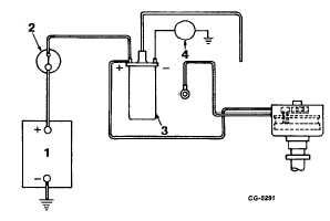
Fig. 53 Testing With Brown Wire Removed
1. Battery
3. Ignition Coil
2. Ignition Switch
4. Voltmeter
7.
Test control unit operation.
Voltmeter should be connected between coil negative
(-) terminal and ground (Figure 53).
With ignition switch "on", place blade of screwdriver
against face of sensor (Figure 54) while observing
voltmeter. Voltage should increase to 12 - 13 volts.
Remove screwdriver blade. Voltage should drop to 5
- 8 volts.
If voltage switches up and down, proceed to step 8.
If voltage does not switch up and down when
screwdriver blade is placed against and then
removed from face of sensor, electronic control unit
in distributor is faulty and must be replaced.
8.
Test Coil Operation
Re-establish the 13 mm (1/2 inch) gap between
extension adapter (connected to coil high tension
cable) and engine (Figure 55).
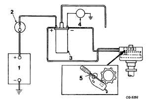
Fig. 54 Testing Electronic Control Unit
Operation
1. Battery
3. Ignition Coil
2. Ignition Switch
4. Voltmeter
5. Screwdriver
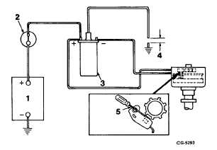
Fig. 55 Testing Coil Operation
1. Battery
3. Ignition Coil
2. Ignition Switch
4. 13 mm (1/2 in.) gap
5. Screwdriver
With ignition switch "on" observe for spark across
gap each time screwdriver blade is placed against
face of sensor.
If no spark occurs, coil is faulty and must be
replaced.
9.
Retest for Spark at Plug.
After
replacing
components,
disconnect
test
equipment. Reinstall shield, rotor and distributor cap
and reconnect coil high tension cable to distributor
cap.
Recheck for spark at spark plug (Step 2).
CGES-145-U Page 26
PRINTED IN UNITED STATES OF AMERICA
|