|
| |
ENGINE DIVISION SERVICE MANUAL
TM 5-4210-230-14&P-1
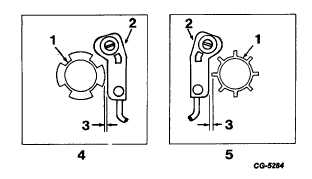
end of tooth (Figure 43). Move sensor as
needed to obtain specified air gap (see
DISTRIBUTOR TEST SPECIFICATIONS).
Tighten sensor mounting screw and recheck air
gap.
Fig. 43 Trigger Wheel-to-Sensor Air Gap
1. Trigger wheel
2. Sensor
3. Air gap
4. 4 cylinder engine
5. 8 cylinder engine
8.
Mount distributor in distributor test stand. (See
Distributor Operation Test).
9.
Operate distributor at 300 RPM (with 12-13 volts
primary input and observe dwell reading. Dwell
should be within specified limits.
a.
If dwell reading is within specified limits,
trigger wheel to-sensor gap is satisfactory.
b.
If dwell reading is not within specified limits,
loosen sensor mounting screw and adjust
trigger wheel-to-sensor air gap as required to
obtain specified dwell. Move sensor toward
trigger wheel to decrease dwell or away from
trigger wheel to increase dwell. Dwell is
affected approximately one-half (½ ) degree
per .025 mm (.001 in.) of sensor movement.
After correct dwell is obtained, tighten sensor
mounting screw.
10.
The mechanical advance mechanism is calibrated at
the factory and no further calibration is required.
11.
Connect test stand vacuum hose to vacuum advance
diaphragm and check operation of vacuum advance.
If advance does not fall within specified vacuum
readings, replace vacuum diaphragm and recheck
vacuum advance operation.
12.
If distributor operation is satisfactory, remove
distributor from test stand and install dielectric shield
(dust cover) and rotor.
CGES-145-U Page 21
PRINTED IN UNITED STATES OF AMERICA
|