|
| |
TRUCK SERVICE MANUAL
TM 5-4210-230-14&P-1
ELECTRICAL
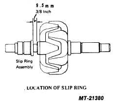
There is no stop on the shaft to prevent the slip rings
from being pressed on too far. It is therefore necessary
to press the slip rings only to a point where there is 9.5
mm (3/8") space between the inner edge of the slip rings
and the rotor (see Fig. 25).
REASSEMBLY
1. If slip ring end bearing has been removed, press a new
bearing in place from the outside of the housing. Bearing
should be installed with seal facing in toward slip rings.
When properly installed, the manufacturer's part number
stamped on the end of the bearing will be facing toward
the outside of the housing.
Bearing should seat against lip on inside end of bearing bore.
After bearing is installed, apply a small amount of grease
(Chevron SRI 2 or equivalent) to rollers.
2. Reinstall heat sinks in slip ring end housing. Be sure that
upper and lower insulating washers are in their proper
location. Install but do not tighten lower heat sink retaining
screws,
lockwashers,
guardwashers
and
insulating
washers (see Fig. 9).
Replacement heat sinks may differ in thickness or appearance
from the original assemblies, but will fit and function
interchangeably.
3. Install terminal bolts and regulator lead wires. Red wire
goes on positive heat sink and black wire goes on
negative. Be sure that mating surfaces of heat sinks,
terminals and terminal bolts are clean and free of paint to
insure a good electrical connection (see Fig. 7).
4. Install two insulating bushings on each terminal bolt and
install regulator housing.
5. Be sure that red and black regulator leads are properly
routed through cutaway section of end housing, and
install and tighten nuts on terminal bolts (see Fig. 4).
5. Tighten lower heat sink screws and check all leads for
proper routing, being sure that no lead is pinched under
heat sink.
6. Reinstall capacitor.
7. Reinstall stator and terminal nuts. It is advisable to align
stator and housing by temporarily installing the through
bolts.
8. Press drive end bearing into housing and reinstall bearing
retainer and four screws.
When installing bearing, press on outer race to avoid
transmitting force through the bearing balls which could
brinnell the bearing.
9. Press drive end housing and bearing onto rotor shaft.
Using a sleeve around the shaft, press on the inner race
to avoid brinnelling the bearing.
10. Install rotor and housing assembly into stator and slip
ring end housing assembly, being sure that mounting
ears are aligned.
11. Install three through bolts and self locking nuts. Torque
to 5.6-6.8 N.m (50-60 in. lbs.). Place a small amount of
grease (Chevron SRI 2 or equivalent) in housing and
reinstall the metal dust cap by carefully pressing it into
place.
12. Install diode trio and three nuts.
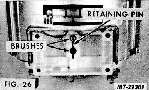
13. Insert outer brush and spring assembly into the housing
and compress the brush spring, using a small
screwdriver or similar tool. While holding the spring
compressed, insert
PRINTED IN UNITED STATES OF AMERICA
Fig. 25
CTS-2743T Page 11
|