|
| |
TRUCK SERVICE MANUAL
TM 5-4210-230-14&P-1
ELECTRICAL
a pin through the hole in the rear of the housing so that
the spring will be held in a compressed position. (A
suitable pin can be made from a piece of 1.6 mm (1/16")
drill rod). Install and compress the remaining brush and
spring assembly in a similar manner. Hold the spring in a
compressed position by pushing the pin farther into the
housing (see Fig. 26).
14. Attach red and black leads to regulator. Attach blue
regulator lead to diode terminal screw by placing the
spade terminal under the head of the screw. Tighten nut
on terminal screw (see Fig. 4). Install regulator.
Be sure that the red and black leads are properly routed
through their slots in the regulator housing. Install four
regulator screws. Withdraw brush retaining pin before
tightening these screws.
15. Install diode trio lead and nut.
16. Install spacer, key, fan, pulley and nut. Torque nut to 95-
108 N.m (70-80 ft. lbs.). Due to the design of the
alternator, a certain amount of shaft end play will be
present in new or rebuilt units. This end play is designed
into the unit and will vary between 0.1 to 0.3 mm (.004 to
.012 inch).
CAUTION
DO NOT FORCE OR POUND PULLEY ON
SHAFT.
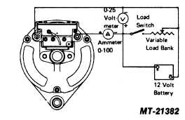
TESTING
Because of the integral regulator used on this
alternator, the test block hookup is very simple, consisting of
connecting the positive and negative output leads. If a
commercial test block is not available, the test setup shown in
Figure 27 may be used.
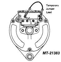
Before beginning the test and after the battery has
been connected, momentarily flash the field by connecting a
jumper between the diode trio terminal and the alternator
positive output terminal (see Fig. 28). This will restore the
residual magnetism which may have been weakened by
handling or repair procedures.
VOLTAGE REGULATOR REPLACEMENT
REMOVAL
1. Remove four screws and carefully lift regulator free of
housing. Remove red and black leads from regulator
noting their position to facilitate assembly of new
regulator (see Fig. 4).
2. Remove lead from diode trio to terminal regulator housing.
Loosen inner nut which will allow blue regulator lead to be
withdrawn from under head of terminal screw. Remove
regulator (see Fig. 4).
3. Lift brush and spring assemblies out of housing (see Fig.
4).
INSTALLATION
1. Install brushes.
When brush springs have been compressed, hold them in
place by passing a pin through the retainer hole (see Fig.
26). A suitable pin can be made from a piece of 1.6 mm
(1/16") drill rod.
2. Attach red and black leads to regulator with shake-proof
spring lockwashers and nuts supplied. Attach blue
regulator lead to diode terminal screw by placing the
space terminal under the head of the screw. Tighten nut
on terminal screw (see Fig. 4). Install regulator.
Continued on Page 14
FIG. 27
FIG. 28
CTS-2743T Page 12
|