|
| |
TRUCK SERVICE MANUAL
TM 5-4210-230-14&P-1
ELECTRICAL
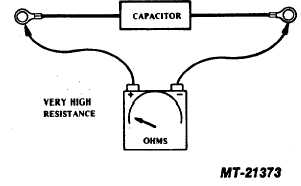
Its value is .5 MFD, and 200 working volts D.C.
In the absence of a capacitor tester, the unit may be checked
for shorts by means of an ohmmeter connected across the
terminals. A low resistance reading indicates a shorted or
leaking capacitor which should be replaced (see Fig. 18).
VOLTAGE REGULATOR TEST
The regulator circuitry contains devices connected in such a
manner that parallel or "sneak" circuits exist making it
impossible to electrically test each individual component, as
several will be in the circuit at the same time. For this reason,
point to point resistance checks with an ohmmeter may be
inconclusive or misleading. The regulator can be most
accurately tested by installing it in an alternator known to be
serviceable.
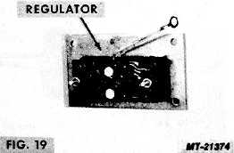
The voltage regulator assembly consists of a number of
individual components such as capacitors, resistors, diodes
and transistors, mounted upon and electrically connected by a
printed circuit panel. Because these components are
permanently fastened to the panel, their replacement is not
recommended. When it has been
determined that a voltage regulator is unserviceable, it should
be discarded and a new assembly installed in its place (see
Fig. 19).
ROTOR TEST
The rotor should be checked for grounds and proper coil
resistance with an ohmmeter.
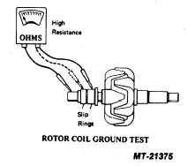
1. With the ohmmeter connected between the rotor shaft and
either slip ring, no reading (infinity) should be obtained. If an
ohmmeter reading other than infinity is obtained, the rotor coil
is grounded and the rotor must be replaced (see Fig. 20).
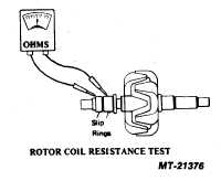
2. Check rotor coil resistance by connecting the ohmmeter
across the two slip rings (see Fig. 21). The resistance of the
rotor should be within the following limits:
2310JB
4.9-5.5 Ohms
2510JB
2.3-2.7 Ohms
2610JB
2.3-2.7 Ohms
2810JB
1.9-2.3 Ohms
Discard
rotors
whose
resistance
values
differ
PRINTED IN UNITED STATES OF AMERICA
FIG. 18
FIG. 20
FIG. 21
CTS-2743T Page 9
|