|
| |
TRUCK SERVICE MANUAL
TM 5-4210-230-14&P-1
ELECTRICAL
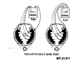
Negative Heat Sink Tests:
1. Connect the negative test lead to the negative heat sink
and touch the positive test lead to each diode terminal. If a
low resistance reading is obtained or if the test lamp lights,
the diode is shorted (see Fig. 15).
2. Reverse the test leads so that the positive test lead is
connected to the negative heat sink. Touch the negative lead
to each of the three diode terminals. A low resistance reading
should be obtained, and if a test light is being used, the lamp
should light. If high resistance is indicated or the lamp does
not light, the diode is open (see Fig. 16).
If a shorted or open diode is detected in the preceding tests,
the entire heat sink assembly should be replaced.
Heat sinks supplied as service replacements may differ
slightly in thickness or general appearance from the original
parts. This will
in no way impair their interchangeability or reliability. To
obtain
the
maximum
serviceability,
several
different
assemblies may be used as replacements. These will be
listed in the appropriate parts list.
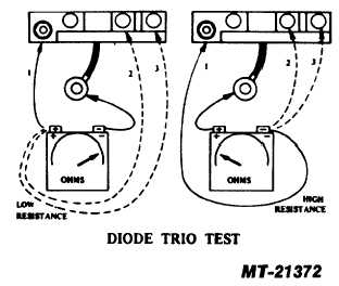
DIODE TRIO TESTS
The diode trio may be tested with the same equipment which
was used to check the diodes in the heat sink assemblies.
1. Connect the negative lead of the tester to the output lead
of the diode trio, and touch the positive tester lead to each of
the three copper terminal pads (see Fig. 17). A low
resistance should be indicated, and if a test lamp is being
used, it should light.
2. Connect the positive terminal of the tester to the output
lead of the diode trio and touch the negative lead to each of
the three copper terminal pads. A high resistance should be
indicated and if a test lamp is being used, it should not light.
Discard any diode trio which does not pass all of these tests.
CAPACITOR TEST
The capacitor connected across the heat sinks may be tested
on a capacitor tester if available.
PRINTED IN UNITED STATES OF AMERICA
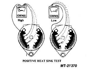
FIG. 13
FIG. 14
FIG. 15
FIG. 16
FIG. 17
CTS-2743T Page 8
|