|
| |
TRUCK SERVICE MANUAL
TM 5-4210-230-14&P-1
ELECTRICAL
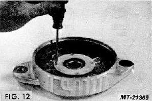
17. Remove four screws and bearing retainer and press
bearing out of drive end housing (see Fig. 12).
COMPONENT TESTING
Before performing these tests, carefully inspect all
parts for wear, cracks, breakage or other mechanical defects.
Discard all damaged parts.
DIODE TESTS
These tests may be performed on heat sink
assemblies without removing them from the end housing. If
they are tested in this manner, remove the stator and be sure
that the red and black leads are disconnected from the
regulator and not touching each other. Be sure the diode trio
has been removed from the A/C studs and disconnect the
capacitor across the lower end of the heat sinks.
Diodes are tested to insure that they only pass
current in one direction. Diodes which do not allow current to
flow in either direction are open while diodes passing current
both ways are shorted. Diodes should be checked with a
diode tester, but in emergencies where one is not available,
an ohmmeter or battery powered test light may be substituted.
Positive Heat Sink Tests:
The positive heat sink is the one to which the positive
output terminal is connected. The square hole in the terminal
end of the positive heat sink is larger than the terminal hole of
the negative heat sink.
1. Connect the positive lead of the diode tester, ohmmeter, or
test light to the positive heat sink and touch the negative
test lead to each of the three diode terminals. A high
resistance should be indicated and if a test light is being
used, it should not light. If any of the three diodes shows
a low resistance, or the test lights, the diode is shorted
(see Fig. 13).
2. Reverse the test leads so that the negative test lead is
connected to the positive heat sink. The positive test lead
should now be touched to each diode terminal and a low
resistance reading should be obtained. If a high
resistance reading is obtained, or the test lamp fails to
light, an open diode is indicated. (See Fig. 14.)
CTS-2743T Page 7
PRINTED IN UNITED STATES OF AMERICA
|