|
| |
TRUCK SERVICE MANUAL
TM 5-4210-230-14&P-1
ELECTRICAL
8.
Remove three nuts which secure stator leads to
terminals and remove stator.
9.
Remove nuts from positive and negative output
terminal bolts and remove the bolts. Note the location
of the red and black regulator leads on the heat sinks
(see Fig. 7).
10.
Remove three hex head screws and remove capacitor
connected between the heat sinks (see Fig. 7).
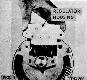
11.
Remove regulator housing. Note location of gasket
which seals brush compartment (see Fig. 8).
12.
Remove terminal stud insulating bushings from
housing. There are two bushings in each terminal hole
(see Fig. 8).
13.
Remove two screws, lockwashers, guardwashers and
insulating washers which retain lower end of heat
sinks. Remove heat sinks. Note location of insulating
washers and bushings (see Fig. 9).
Fig. 9
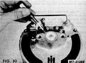
14. Pry flanged dust cap out of housing (see Fig. 10).
15. Slip ring end bearing replacement should seldom be
required. If it should become necessary, however,
press the bearing from the inside of the housing
outward, using Snap-On Tool Co., No. CG-40-11 with
CG-40-4 (see Fig. 11).
16. Using a puller or arbor press, remove the drive end
housing and bearing assembly from the rotor shaft
(see Fig. 11A).
CTS-2743 Page 6
PRINTED IN UNITED STATES OF AMERICA
|