|
| |
TRUCK SERVICE MANUAL
TM 5-4210-230-14&P-1
ELECTRICAL
The voltage regulator used in these alternators is a solid
state device and for this reason will normally have an extremely
long life. It can, however, be, damaged by mechanical or
electrical abuse.
If the system polarity is inadvertently reversed by
installing a battery backwards, boosting or jump starting with
the jumper connected backwards, or reversing the positive and
negative alternator output leads when changing an alternator,
the voltage regulator will be damaged. Although the polarity
reversal may only be momentary and may not damage the
alternator diodes, the regulator will still be damaged.
ADJUSTMENT
Prior
to
adjusting
alternator
voltage,
the
wiring,
connections and belt tension should be checked and repaired as
needed. The batteries should be fully charged and the engine
should be running at a fast idle. Turn off all vehicle loads such
as lights, radios, heaters. air conditioners, etc. when checking
or adjusting voltage. An accurate voltmeter should be
connected across the batteries to determine the charging
voltage. Do not rely on dash mounted vehicle instruments.
These are excellent indicators but usually lack the extreme
accuracy required for regulator adjustment. Remove nylon
screw (plug) from the regulator (see Fig. 1), and with a small
screwdriver carefully turn the adjusting screw clockwise to raise
or counter-clockwise to lower the voltage. The ideal voltage
setting will be a value which maintains a fully charged battery
without resulting ill all excessive usage of battery water.
When turning the voltage adjustment screw, do not
attempt to force it past its stop as damage will result. Be sure
to replace the screw (plug) in the regulator adjustment hole to
prevent the entrance of water and dirt.
DISASSEMBLY
1.
Remove pulley nut, pulley, fan, key and spacer. Use a
suitable puller to avoid damage to the shaft and
threads.
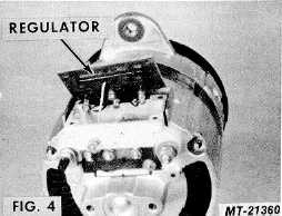
2.
Remove four screws and carefully lift regulator free of
housing. Remove red and black leads from regulator,
noting their position to facilitate reassembly (see Fig.
4).
3.
Remove lead from diode trio to terminal on regulator
housing. Loosen inner nut, which will allow blue
regulator lead to be withdrawn from under head of
terminal screw. Remove regulator (see Fig. 4).
4.
Lift brush and spring assemblies out of housing (see
Fig. 4).
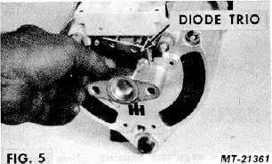
5.
Remove three nuts and lift diode trio off of A/C
terminal studs (see Fig. 5).
6.
Remove three self locking nuts and through bolts.
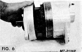
7.
Remove rotor and drive end housing assembly from
stator and slip ring end housing assembly. If drive end
housing binds on stator, loosen by tapping gently on
mounting ear with fibre hammer. Be sure that drive
end housing separates from stator and that stator
remains attached to slip ring end housing to avoid
damage to stator leads (see Fig. 6).
CTS-2743T Page 5
PRINTED IN UNITED STATES OF AMERICA
|