|
| |
TRUCK SERVICE MANUAL
TM 5-4210-230-14&P-1
ELECTRICAL
TROUBLE SHOOTING
Before performing trouble shooting procedures on the
vehicle, be absolutely certain that wiring is not defective and
belts are not slipping, as these problems are common.
To determine if the problem lies in the regulator or the
alternator, connect an accurate voltmeter across the battery
with the engine stopped, and note the reading. The engine
should now be started. If the voltmeter reading rises
excessively, the charging system may be defective or may
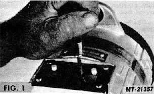
require adjustment. Remove the nylon screw from the regulator
and with the engine at approximately 1000 RPM, attempt to
bring the voltage to its proper value (13.8-14.2 V approximately)
by turning the adjusting screw back and forth with a small
screwdriver (see Fig. 1).
If the voltage is excessively high and cannot be lowered
by means of the adjustment, the regulator is probably defective
and should be replaced. If the output voltage cannot be raised,
either the alternator, regulator or diode trio may be at fault. To
determine if the fault is in the regulator or in the alternator,
perform the following test.
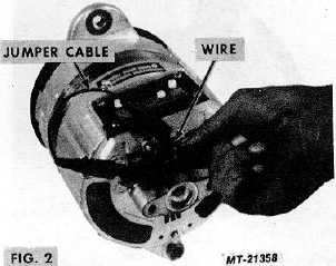
Connect one end of a short jumper lead to the negative
alternator output terminal and connect the other end of the
jumper to a short stiff piece of wire at least 38 mm (1 1/2") long.
A piece of paper clip wire will be suitable. Insert this wire into
the small hole in the end of the brush holder so that it firmly
contacts the outer brush terminal. (see Fig. 2).
If the voltmeter reading now rises with the engine at a
fast idle, the alternator is OK and the fault is in the regulator or
diode trio. Remove the diode trio and test (see "COMPONENT
TESTING"). If the diode trio tests OK, the regulator should be
replaced.
If the voltage fails to rise when performing this test,
remove the regulator and carefully inspect it for a printed circuit
track which has burned open. If this condition is found, replace
the regulator. Check the brush spring caps and their contact
screws for dirt or corrosion and clean if necessary. If the
alternator does not operate after performing either or both of
these operations, the alternator should be removed for repair or
replacement.
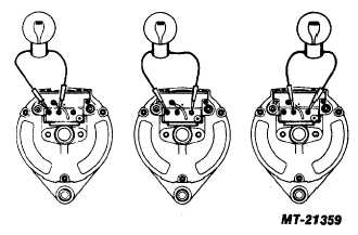
FIG. 3
The alternator may also be checked for output across
each phase by using a test light as shown in Fig. 3. The test
light should be constructed from a two filament sealed beam
unit connected in such a manner that the filaments are in
parallel. Such a light will act as a load a as well as an indicator,
and should light with equal brilliancy on each phase. If the
lamp is noticeably dimmer on one or two phases, a defective
diode trio or power diode is indicated. If the diode trio tests OK,
then the alternator must be removed and dismantled for further
tests.
CTS-2743T Page 4
PRINTED IN UNITED STATES OF AMERICA
|