|
| |
TRUCK SERVICE MANUAL
TM 5-4210-230-14&P-1
ELECTRICAL
DESCRIPTION
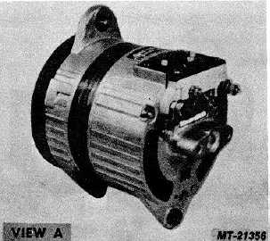
The IH heavy duty alternators (View A) are 14 volt self
load limiting alternators which feature a fully adjustable, built-in
solid state voltage regulator.
The alternators incorporate a 22.2 mm (7/8") straight
shaft, a large ball bearing at the drive end and a roller bearing
at the slip ring end. The alternators have a two leg swivel
mounting, one leg of which is equipped with a slideable
bushing. The rotor shaft may be rotated in either direction.
Six silicone diodes mounted in heat sinks convert
alternating current from the delta wound stator into direct
current. A capacitor connected between the heat sinks assists
in suppressing transient voltage spikes which could possibly
injure the diodes.
The brushes and voltage regulator are located in a
waterproof housing and may be removed for replacement or
inspection without dismantling the entire machine. An external
relay terminal is also provided for operation of chargelight
relays or other accessories which might require power from
such a source.
The alternators have ungrounded output terminals so
that they may be used on either positive or negative ground
systems. Aside from connecting the proper vehicle wires to the
correct output terminals, no other wiring is required on the
alternator, eliminating field relays or ignition switch connections.
OPERATION
Current is produced by rotating a magnet called a rotor
inside a stationary winding called a stator.
The rotor is electrically magnetized by a small current
flowing through it via brushes riding on smooth slip rings.
Alternating current is produced as the magnet poles of
the rotor pass through the coil windings of the stator. For
increased capacity, there are twelve (12) magnetic poles
incorporated into the rotor and three (3) separate windings in
the stator. Since alternating current is produced as the rotor
passes the coil windings of the stator, increased engine speed
produces more current.
The battery stores only direct current and cannot use
alternating current. For this reason, rectifier assemblies are
used to convert alternating current produced in the stator to
direct current. Rectifiers consist of silicon diodes which function
as electrical switches and permit current flow in only one
direction.
The rectifier diodes are mounted in aluminum castings,
called heat sinks, which are finned to dissipate heat.
A built-in solid state voltage regulator controls alternator
output and the battery's state of charge. The diode trio, so
called because it consists of three (3) diodes, converts a small
amount of alternator current from the stator into direct current
which is used as a signal to turn on the regulator.
The regulator senses when the battery has received
sufficient charge and then reduces the "field" (magnetizing)
current flow to the rotor. Reducing the field current flow, in turn,
reduces alternator output.
When headlights and/or accessories place a load on the
battery, the regulator increases the field current flow to the
rotor, thereby increasing alternator output.
PREVENTIVE MAINTENANCE
Mounting hardware including brackets and drive belts
must be periodically inspected and adjustments or repairs
performed as required. It is important that mounting bolts and
nuts be kept securely tightened to maintain belt alignment and
prevent vibration damage which will occur if mounting bolts
work loose.
Vehicle wiring must be inspected at periodic intervals for
loose or corroded connections and repairs made as needed.
CTS-2743T Page 3
PRINTED IN UNITED STATES OF AMERICA
|