|
| |
TRUCK SERVICE MANUAL
TM 5-4210-230-14&P-1
The master cylinder (Fig. 2) is not equipped with a
residual check valve. The valve is located in the power
cylinder when this master cylinder is used.
Inspect the master cylinder at the time of making
brake adjustment for correct fluid level. Fluid should be within
6.4 to 12.7 mm (1/4 to 1/2") from the top of the filler neck. Do
not fill the supply reservoir to the top of the filler neck. When
removing the supply reservoir filler cap, extreme care must be
used to prevent dirt or moisture from entering the master
cylinder.
POWER CYLINDER
The power cylinder assembly, whether it be a
vacuum power booster or a compressed air booster, is
designed to supplement the usual manual brake operation.
The power brake units often appear different in shape and
arrangement and internal components may also appear
different; however, all function in the same manner. The
operating force is controlled by a valve mechanism and
exerted against a stroking device which converts it into
pressure for braking.
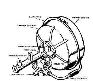
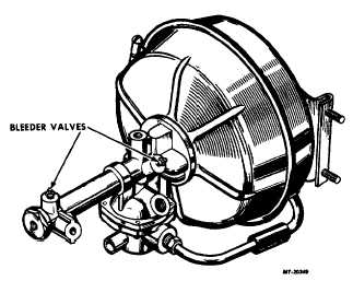
Figures 3 and 4 illustrate two typical type vacuum
power units. Complete detailed instructions pertaining to
operation, description and overhaul for a particular unit may
be found elsewhere in this service manual.
Fig. 3. Vacuum Power Cylinder
Fig. 4. Vacuum Power Cylinder
RESIDUAL CHECK VALVE
The residual check valve (Fig. 1), item L) maintains
41 to 124 kPa (6 to 18 psi) hydraulic pressure in the hydraulic
system beyond the master cylinder to provide sealing of wheel
cylinder piston cups with released brakes. The valve isolates a
momentary vacuum which may occur in the master cylinder.
This pressure will not cause the brake shoes to drag, as the
shoe return springs overcome the residual pressure in the
hydraulic system.
During manual bleeding the valve assists pumping
fluid through the system by closing every time the brake pedal
is released. If the valve should fail to hold the residual
pressure, a very small leak or even road shock over a period
of time could cause increased pedal stroke and a spongy
pedal feel.
The residual check valve action can be inspected by
cracking a bleeder screw open. A small spurt of fluid will
indicate residual pressure.
On vehicles equipped with certain type power
cylinders, the check valve is located in the power cylinder
slave cylinder tube; where this is the case, no check valve is
used in the master cylinder. (Refer to power cylinder section
specifications for the particular unit involved.)
CTS-2055S Chapter II Page 4
PRINTED IN UNITED STATES OF AMERICA
|