|
| |
TRUCK SERVICE MANUAL
TM 5-4210-230-14&P-1
MASTER CYLINDER
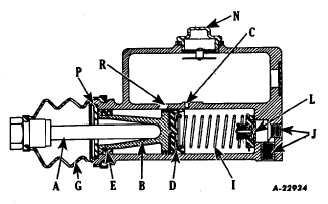
The combination or compensating type master
cylinder (Fig. 1) consists of a barrel and tank casting,
residual check valve (L), piston cup return spring (I), piston
cup (D), piston (B), piston stop (P), boot (G) and push rod (A).
Fig. 1. Typical Master Cylinder
The fluid reservoir or supply tank is cast integrally
over the master cylinder barrel. A combination filler and
breather plug (N) permits atmospheric pressure on the
reserve fluid at all times.
Depression of the pedal causes piston (B) and cup
(D) to move forward in the cylinder barrel. A very small
forward movement of cup (D) closes compensating port (C)
and the pressure stroke commences.
Minimal pressure is built up until the fluid displaced
has caused all shoes to go into contact with their drums.
Additional pressure on the pedal produces higher hydraulic
pressure within the brake system.
Removal of the operator's foot from the brake pedal
after each brake application permits the brake pedal and push
rod (A) to return independently to their off position.
The return of piston (B) and cup (D) is accomplished
by the piston return spring (I).
The piston for this type of unit is designed to carry a
primary cup (D) and a secondary cup (E). The construction of
the piston is such that
reserve fluid from the tank passes through vent (R) in a
recessed area. Thus, we have fluid on both sides of the
primary cup. The secondary cup (E) is merely a seal to
prevent loss of reserve fluid into boot (G).
The primary compensating function is to maintain a
constant volume of fluid in the system at all times, regardless
of expansion (heat) or contraction (cold). The secondary
compensating function is the replacement of additional fluid
into the system to counterbalance any loss due to gravity
seepage.
The return of piston (B) and cup (D) can be faster in
displaced volume than the return of the fluid through fitting (J)
into the master cylinder. A momentary vacuum is created in
the cylinder barrel and additional fluid is drawn into the
system through the drilled holes in piston (B) and past the lip
of cup (D). The operating fluid returns more slowly from the
wheel cylinders and lines back into the master cylinder barrel.
Any excess is bypassed by port (C) into the reservoir. Thus,
we have a cylinder full of fluid for the next brake application.
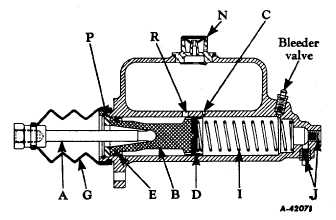
Fig. 2 illustrates a master cylinder equipped with a
bleeder valve located in the cylinder barrel. This bleeder valve
is commonly used in the larger stroke master cylinders. Its
purpose is for expelling any air that may be trapped in the
upper head end of the cylinder barrel.
Fig. 2. Typical Master Cylinder with Bleeder Valve
CTS-2055S Chapter II Page 3
PRINTED IN UNITED STATES OF AMERICA
|