|
| |
TRUCK SERVICE MANUAL
TM 5-4210-230-14&P-1
BODIES AND CABS
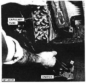
Fig. 58 Withdrawing Thermostatic Control Switch Capillary
Tube from Housing
Installation:
1.
Insert
thermostatic
temperature
control
switch
capillary tube through hole in seal at bottom of
heater/evaporator unit housing.
2.
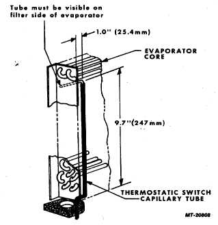
Insert end of capillary tube into evaporator core at
location shown in Figure 59. (Remove air filter seal
strip and air filter to check position of end of capillary
tube.)
3.
Connect control cable to switch lever and install
retainer clip.
4.
Position switch on bracket and install switch
mounting screws.
5.
Position cable mounting ta on switch bracket and
install mounting screw.
6.
Check control cable adjustment as outlined under
"Control Cable Adjustment".
7.
Install heater core as follows:
a.
Make sure gaskets are in place on ends of
heater core.
b.
Align slot in heater core frame with rivet at
front of housing and push core into position.
c.
Install heater core mounting screws.
Fig. 59 Capillary Tube Location in Evaporator
8.
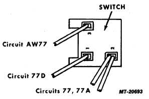
Connect wiring connectors to thermostatic control
switch. Make sure connectors are located properly
(Fig. 60).
Fig. 60 Thermostatic Control Switch Wiring Connector
Locations
9.
Check operation of thermostatic control switch.
10.
Install covers on heater/evaporator unit and
instrument panel.
CTS-2731 Page 39
PRINTED IN UNITED STATES OF AMERICA
|