|
| |
TRUCK SERVICE MANUAL
TM 5-4210-230-14&P-1
BODIES AND CABS
CAUTION
A small amount of refrigerant may escape from adapter while
low pressure switch is being removed.
Installation:
1.
Lubricate threads of low pressure switch with
refrigerant oil and position switch on adapter.
2.
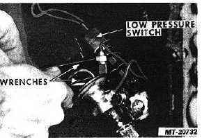
Using two wrenches, tighten low pressure switch.
3.
Connect low pressure switch wires to wiring harness.
4.
Install
covers
on
heater/evaporator
unit
and
instrument panel.
Fig. 55 Removing Low Pressure Switch
THERMOSTATIC TEMPERATURE CONTROL SWITCH
Removal:
1.
Make sure key switch and A/C lever are "OFF" .
2.
Remove cover from right side of instrument panel.
3.
Remove cover from heater/evaporator unit.
4.
Disconnect wiring connectors (3) from thermostatic
control switch.
IMPORTANT
Before disconnecting wires, note circuit number locations to
assure correct reassembly.
5.
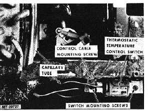
Remove control cable mounting screw (Fig. 56).
6.
Remove thermostatic control switch mounting screws
and remove switch from bracket (Fig. 56).
Fig. 56 Thermostatic Control Switch Mounting Details
7.
Remove retainer clip and disconnect control cable
from switch lever.
8.
Remove heater core mounting screws. (Do not
disconnect hoses from heater core.) Pull heater core
outward to disengage mounting slot. Move heater
core down and to the right. (This will permit
withdrawal of thermostatic control switch capillary
tube from evaporator core.
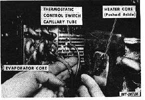
9.
Withdraw thermostatic control switch capillary tube
from evaporator core (Fig. 57).
Fig. 57 Withdrawing Thermostatic Control Switch Capillary
Tube from Evaporator Core
CTS-2731 Page 38
PRINTED IN UNITED STATES OF AMERICA
|