|
| |
TRUCK SERVICE MANUAL
TM 5-4210-230-14&P-1
BODIES AND CABS
9.
Remove control cable mounting bracket.
10.
Disconnect -adjustable link from blend air door.
11.
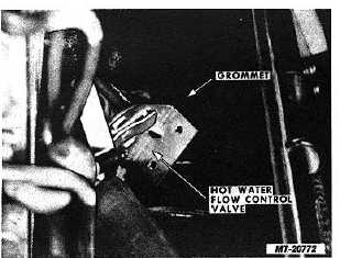
Rotate control valve assembly as necessary to
withdraw lower neck of valve through grommet in
bottom of heater/evaporator unit housing. Remove
valve (Fig. 54).
Fig. 54 Removing Hot Water Flow Control Valve from Unit
Housing
12.
Disconnect hose clamp and remove valve-to-heater
core hose from valve.
13.
Inspect all hoses and control valve inlet neck
grommet in bottom of unit housing. Replace if
damaged or deteriorated.
Installation:
1.
Position control valve-to-heater cover hose on valve
and tighten hose clamp.
2.
Insert lower neck of flow control valve through
grommet in bottom of heater/evaporator unit housing
and rotate valve assembly into position.
3.
Connect adjustable link to blend air door.
4.
Position flange of control cable mounting bracket
under mounting flange of control valve.
5.
Install and tighten valve mounting screws.
6.
Connect inlet hose to lower neck of flow control valve
and tighten hose clamp.
7.
Install heater core as follows:
a.
Make sure gaskets are in position on ends of
heater core.
b.
Open blend air door.
c.
Position heater core into housing. Align slot in
heater core frame with rivet at front of housing
and push core into position.
d.
Install heater core mounting screws.
e.
Connect hoses to heater core and tighten hose
clamps.
8.
Connect control cable to blend air door and install
cable mounting screw.
9.
Adjust control cable as outlined under "Control Cable
Adjustment".
10.
Refill engine cooling system.
11.
Set heater (HTR) control at "HOT". Operate engine
and check for coolant leaks and for proper operation
of flow control valve.
12.
Install
covers
on
heater/evaporator
unit
and
instrument panel.
13.
Lower hood and fender assembly.
LOW PRESSURE SWITCH
The low pressure switch can be replaced without
discharging the refrigerant from the air conditioning system.
A spring-loaded valve in the switch mounting adapter on the
evaporator outlet pipe prevents loss of refrigerant when switch
is removed.
Removal:
1.
Make sure key switch is "OFF".
2.
Remove cover from right side of instrument panel.
3.
Remove cover from heater/evaporator unit.
4.
Disconnect low pressure switch wires from wiring
harness.
5.
Using two wrenches, remove low pressure switch
from adapter on evaporator outlet pipe (Fig. 55).
CTS-2731 Page 37
PRINTED IN UNITED STATES OF AMERICA
|