|
| |
TRUCK SERVICE MANUAL
TM 5-4210-230-14&P-1
BODIES AND CABS
(This will permit access to front evaporator core
mounting
screws
and
permit
withdrawal
of
thermostatic temperature control switch capillary
tube 'from evaporator core.)(See Figure 57.)
11.
Withdraw thermostatic temperature control switch
capillary tube from evaporator core.
12.
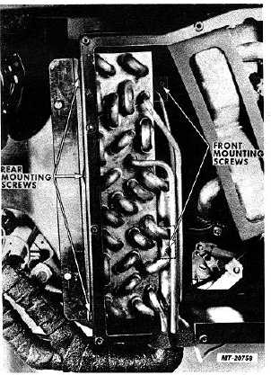
Remove evaporator core mounting screws (Fig. 47).
13.
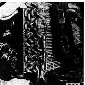
Remove evaporator core from unit housing (Fig. 48).
14.
Remove low pressure switch and expansion valve
from evaporator core.
Fig. 47 Evaporator Core Mounting Screws
Installation:
1.
Install expansion valve and low pressure switch on
evaporator core. (Refer to "Expansion Valve" and
"Low Pressure Switch".)
Fig. 48 Removing Evaporator Core
2.
Position evaporator core in unit housing.
Replace seal surrounding evaporator inlet and outlet
pipes in bottom of unit housing if damaged.
3.
Install evaporator core mounting screws.
4.
Position thermostatic temperature control switch
capillary
tube
in
evaporator
core.
(Refer
to
"Thermostatic Temperature Control Switch".)
5.
Install heater core as follows:
a.
Make sure gaskets are on ends of heater core.
b.
Align slot in heater core fume with rivet at front of
housing and push core into position.
c.
Install heater core mounting screws.
6.
Install air filter and seal mounting strip on blower
housing.
7.
Install clamp, bolt and nut to secure expansion valve
to bracket on blower housing.
8.
Connect low pressure switch wires to wiring harness
9.
Lubricate threads with refrigerant oil and connect
inlet and outlet hoses to evaporator unit inlet and
outlet tubes.
CTS-2731 Page 32
PRINTED IN UNITED STATES OF AMERICA
|