|
| |
TRUCK SERVICE MANUAL
TM 5-4210-230-14&P-1
BODIES AND CABS
6.
Adjust control cable(s) as outlined under "Control
Cable Adjustment".
7.
Install
covers
on
heater/evaporator
unit
and
instrument panel.
8.
Connect battery cable to battery.
CONTROL CABLE ADJUSTMENT (Refer to Figure 45)
1.
Remove cover from right side of instrument panel.
2.
Remove cover from heater/evaporator unit.
3.
Set control panel assembly levers to the extreme
right:
a.
A/C lever at "COLD".
b.
HTR lever at "HOT" and in detent.
c.
AIR OUTLET lever at "CAB" and in detent.
IMPORTANT
These lever positions must be maintained during adjustment.
4.
Rotate cable adjusters (expand cables) to obtain
mid-travel position of:
a.
Thermostatic temperature control switch.
b.
Blend air door.
c.
Defrost door crank.
5.
Rotate cable adjusters (shorten cables) as needed to
obtain the following settings with cables free from
binding:
a.
Thermostatic temperature control switch at "COLD"
position.
b.
Blend air door closed about 20 percent compression
of door seal and hot water flow control valve in "ON"
position.
c.
Defrost door crank at "CAB" position.
6.
Operate control panel levers several times and check
to assure that proper adjustment is maintained.
If necessary, repeat Steps 3, 4 and 5 to obtain proper
adjustment.
7.
Install
covers
on
heater/evaporator
unit
and
instrument panel.
EVAPORATOR CORE
Removal:
1.
Raise hood and fender assembly.
2.
Discharge air conditioning system as outlined under
SERVICE OPERATIONS.
3.
Remove cover from right side of instrument panel.
4.
Remove cover from heater/evaporator unit.
5.
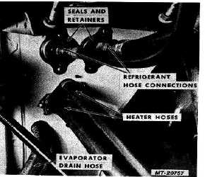
Remove dash panel seal retainers and seals
surrounding evaporator unit inlet and outlet tubes
(Fig. 46).
6.
Disconnect inlet and outlet hoses from evaporator
unit inlet and outlet tubes (Fig. 46).
Fig. 46 Evaporator Dash Panel Connections
7.
Disconnect low pressure switch wires from wiring
harness.
8.
Remove bolt and nut from clamp securing expansion
valve to bracket on blower housing.
9.
Remove air filter seal mounting strip and air filter
from blower housing (Fig. 34).
10.
Remove heater core mounting screws. (Do not
disconnect hoses from heater core.) Pull heater core
outward to disengage mounting slot. Move heater
core down and to the right.
CTS-2731 Page 31
PRINTED IN UNITED STATES OF AMERICA
|