|
| |
TRUCK SERVICE MANUAL
TM 5-4210-230-14&P-1
BODIES AND CABS
10.
Install dash panel seals and retainers surrounding
evaporator inlet and outlet tubes.
11.
Evacuate and charge air conditioning system as
outlined under SERVICE OPERATIONS.
12.
Install
covers
on
heater/evaporator
unit
and
instrument panel.
13.
Lower hood and fender assembly.
EXPANSION VALVE
Removal:
1.
Make sure key switch is "OFF".
2.
Raise hood and fender assembly.
3.
Discharge air conditioning system as outlined under
SERVICE OPERATIONS.
4.
Remove cover from right side of instrument panel.
5.
Remove cover from heater/evaporator unit.
6.
Disconnect wiring harness connector from blower
resistor located on bottom of blower housing.
7.
Remove insulated tape from expansion valve and
evaporator inlet and outlet tubes.
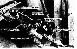
8.
Disconnect expansion valve equalizer line from fitting
on evaporator outlet tube (Fig. 49).
9.
Remove screw and clamp securing expansion valve
feeler bulb to evaporator outlet tube.
10.
Disconnect
expansion
valve
inlet
tube
from
expansion valve.
11.
Remove bolt, nut and clamp securing expansion
valve to bracket on blower housing.
12.
Using two wrenches, disconnect expansion valve
from evaporator core inlet tube. Remove expansion
valve.
Installation:
1.
Lubricate threads with refrigerant oil and connect
expansion valve to evaporator core inlet tube.
Tighten fitting using two wrenches.
2.
Install clamp, bolt and nut' securing expansion valve
to bracket on blower housing.
3.
Lubricate threads with refrigerant oil and connect
expansion valve inlet tube to expansion valve.
Tighten nut to 11-14 N.m (15-20 ft.lbs.).
Fig. 49 Removing Expansion Valve
4.
Position expansion valve feeler bulb on evaporator
core outlet tube and secure with clamp and screw.
5.
Lubricate threads with refrigerant oil and connect
expansion valve equalizer line to fitting in evaporator
outlet tube. Using two wrenches tighten fittings to 7-
11 N.m (10-15 ft. lbs.) torque.
6.
Wrap expansion valve and evaporator inlet and outlet
tubes with insulated tape.
7.
Connect wiring harness connector to blower resistor.
8.
Evacuate and charge air conditioning system as
outlined under SERVICE OPERATIONS.
9.
Install
covers
on
heater/evaporator
unit
and
instrument panel.
10.
Lower hood andfender assembly.
FAN DRIVE OVERRIDE SWITCH
The fan drive override switch can be replaced without
discharging the refrigerant from the air conditioning system.
A spring-loaded valve in the compressor discharge service
port prevents loss of refrigerant when switch is removed.
Removal:
1.
Raise hood and fender assembly.
2.
Make sure key switch is '"OFF".
3.
Disconnect fan drive override switch wires from
engine wiring harness.
CTS-2731 Page 33
PRINTED IN UNITED STATES OF AMERICA
|