|
| |
TRUCK SERVICE MANUAL
TM 5-4210-230-14&P-1
BODIES AND CABS
Air Control Cable
a.
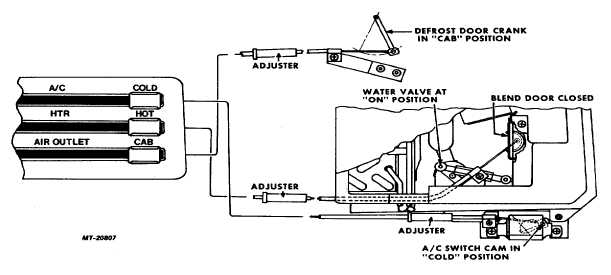
Remove control cable mounting screw from
mounting bracket (Fig. 45).
b.
Remove retainer clip and disconnect cable
from defrost door crank.
7.
Note cable routing and withdraw cable(s) from under
instrument panel.
Installation:
1.
Route cable(s) under instrument panel.
2.
Connect cable(s) to control lever(s) of control
assembly and install retainer clip(s).
Install cable(s) with longest end from adjuster toward
control assembly.
Follow cable color code listed above, under Step 5 of
Removal Procedure.
3.
Install cable mounting screw(s).
4.
Position control assembly in instrument panel and
install trim plate and mounting screws.
5.
Connect opposite end of cable(s) as follows: (Follow
color code.)
Air Conditioning (A/C) Cable
a.
Connect cable to switch lever and install retainer clip.
b.
Position switch on bracket and install mounting
screws.
c.
Position cable mounting tab on switch bracket and
install mounting screw.
Heater (HTR) Cable
a.
Insert cable through hole in heater/ evaporator unit
housing.
b.
Connect cable to blend air door.
c.
Position cable mounting tab on cable mounting
bracket and install mounting screw.
d.
Seal cable hole in heater/evaporator unit housing
with body sealer after adjusting cable, Step 6.
Air Control Cable
a.
Connect cable to defrost door crank and install
retainer clip.
b.
Position cable mounting tab on mounting bracket
and install mounting screw.
Fig. 45 Control Cable Adjustment Positions
CTS-2731 Page 30
PRINTED IN UNITED STATES OF AMERICA
|

