|
| |
TRUCK SERVICE MANUAL
TM 5-4210-230-14&P-1
BODIES AND CABS
5.
Turn key and blower fan switches "ON" and check
motor
operation.
Turn
switches
"OFF"
after
operation check.
6.
Install
covers
on
heater/evaporator
unit
and
instrument panel.
BLOWER RESISTOR
Removal:
1.
On vehicles equipped with air conditioning:
a.
Remove cover from right side of instrument
panel.
b.
Remove cover from heater/evaporator unit.
Cover removal is not required on vehicles with heater only.
2.
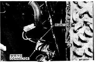
Disconnect wiring harness connector from resistor.
3.
Remove resistor mounting screws and remove
resistor from blower housing (Fig. 39).
Fig. 39 Blower Resistor Removal
Installation:
1.
Position resistor in blower housing. Make sure
resistor terminal locations correspond with wiring
harness terminals. Install mounting screws.
2.
Connect wiring harness connector to resistor.
3.
Turn key switch "ON". Operate blower switch and
check resistor operation. Turn key switch "OFF" after
operation check.
4.
Install
covers
on
heater/evaporator
unit
and
instrument panel.
BLOWER SWITCH
Removal:
1.
Make sure key switch is "OFF".
2.
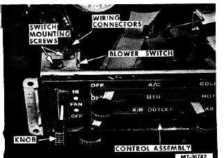
Pull knob from blower switch lever (Fig. 40).
3.
Remove control assembly mounting screws. Remove
control assembly trim plate. Pull control assembly
outward. (It may be necessary to remove ash tray to
allow movement of control assembly.)
4.
Disconnect wiring harness connector from blower
switch.
5.
Remove blower switch mounting screws and remove
switch from control assembly.
Fig. 40 Blower Switch
Installation:
1.
Position blower switch on control assembly and
install switch mounting screws.
2.
Connect wiring harness connector to blower switch.
3.
Position control assembly in instrument panel and
install trim plate and mounting screws.
4.
Push knob onto blower switch lever.
5.
Turn key switch "ON", and check operation of blower
switch. Turn key switch "OFF" after operation test.
CTS-2731 Page 26
PRINTED IN UNITED STATES OF AMERICA
|