|
| |
TRUCK SERVICE MANUAL
TM 5-4210-230-14&P-1
BODIES AND CABS
Make sure control cables are properly adjusted. (See
control
cable
adjustment
instructions
outlined
elsewhere in this section. )
2.
It is most important that all refrigerant fittings and
"O" rings be lubricated with refrigeration oil to allow
the connections to seat squarely and to be tightened
evenly to the specified torque. It is nearly impossible
to attain the correct torque with a dry fitting.
Do not attempt to disconnect or reconnect refrigerant
fittings with only one wrench. Always use a back-up
wrench when loosening or tightening fittings to
prevent damage to hoses, lines or components.
When tightening refrigerant connections, use only a
torque wrench known to be accurate. It should be
noted that torque values specified in the "Torque
Chart" are for original components with fittings
manufactured from specific materials; i.e. brass,
aluminum, etc. These torque values may not be
correct for substitute components. Use only genuine
IH replacement parts.
3.
Be certain that the evaporator core temperature
control sensing bulb is properly inserted into the
evaporator core.
4.
The expansion valve refrigerant temperature sensing
tube must be securely attached to the evaporator
refrigerant outlet tube. Also, the temperature sensing
tube and expansion valve must be tightly wrapped
with insulating tape to prevent the ambient
tempeature from affecting correct sensing of the
temperature of the refrigerant leaving the evaporator.
5.
All refrigerant hose and tubing support clamps and
strap locks must be reinstalled in their original
positions.
6.
The freon compressor oil level must be maintained
as specified. (See SPECIFICATIONS and "Checking
Compressor
Oil
Level"
under
SERVICE
OPERATIONS.)
7.
Last but certainly not least is cleanliness. When
removing components of the air conditioning system,
all openings should be immediately covered or
plugged during removal and remain so until
reinstallation to prevent the entry of dirt, moisture or
other foreign material.
BLOWER MOTOR AND FAN
Removal:
1.
Make sure key and blower fan switches are "OFF ".
2.
Remove cover from right side of instrument panel.
3.
Remove cover from heater/evaporator unit.
4.
Disconnect blower motor wiring connector and
ground wire.
5.
Disconnect motor cooling air hose from blower
housing (where equipped).
6.
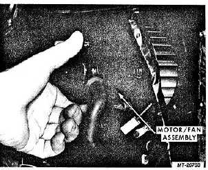
Remove mounting screws and remove motor/ fan
assembly from blower housing (Fig. 38).
7.
Remove fan from motor shaft as follows:
a.
Remove fan lock nut.
b.
Remove fan from motor shaft.
c.
Pry metal spacer from motor side of fan.
Fig. 38 Blower Motor/Fan Removal
Installation:
1.
Install fan on motor shaft as follows:
a.
Position metal spacer in shaft hole (motor
side) of fan.
b.
Position fan on motor shaft.
c.
Install fan lock nut and tighten to 1.4 to 1.7
N.m (12-15 in.lbs.).
2.
Install motor/fan assembly on blower housing and
install mounting screws.
3.
Connect motor cooling air hose to outlet on blower
housing (where equipped).
4.
Connect blower wiring connector and ground wire.
CTS-2731 Page 25
PRINTED IN UNITED STATES OF AMERICA
|

