|
| |
TRUCK SERVICE MANUAL
TM 5-4210-230-14&P-1
Driven Clutch Members
Two identical driven clutch members are
located on either side of the spider and center cam
assembly. Each has a set of clutch teeth to match the
clutch teeth on the spider through which driving torque is
transmitted. Radially inward from the driven clutch
teeth on models using internal spring are cams which
mesh with the cams of the center cam member. These
cams have been eliminated on the models using the
external spring. The internal diameter of each driven
clutch member has splines which engage the external
splines of the splined side members.
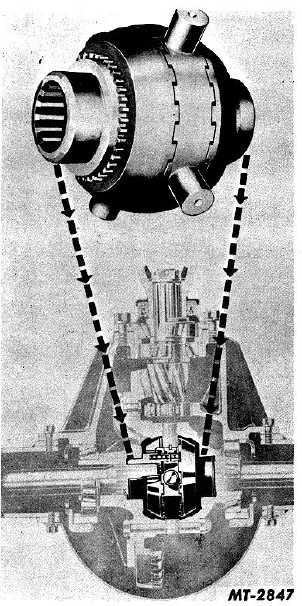
Fig. 36 Typical Installation of NoSPIN Unit
(Cross Sectional View)
Spring Retainers and Springs
Models with Internal Springs:
Spring retainers are inserted into the outer ends
of driven clutch member. The bowl side of these
retainers is mounted first through the outer side of the
driven clutch members. The flanged portion of the
spring retainers pass through the internal splines to rest
on the mating flanges of the driven clutch members.
The springs are mounted in spring retainers after
assembly and thrust against their inner cupped ends.
Models with External Springs:
Spring retainers fit over the side gear, passing
through external splines to seat against the shoulder on
the side gear. Springs fit between the driven clutch and
outer flanged surface of the spring retainer. Splined
Members These two splined side members are splined
internally to receive the truck axle shafts. The inner
hubs of the splined side members are inserted in the
outer ends of the springs. The external splines of the
splined side rembers engage the internal splines of
driven clutch members on each side of the completed
assembly.
OPERATION
Straight Forward Driving
When a vehicle is being driven in a straight
forward direction, the clutch teeth on both sides of the
spider assembly are fully engaged with the clutch teeth
on each driven clutch member. Likewise, the fixed
cams of the driven clutch members are fully meshed
with the cam surfaces of the floating center cam ring
mounted on the inside diameter of the spider, as
described previously.
Engagement of the driving and driven clutch
teeth is assured by the pressure of the two springs which
force the driven clutch members inwardly against the
spider and also by the positive locking action developed
by the mating undercuts on the driving faces of the
clutch teeth, Fig. 37.
In this condition, both clutches remain fully
engaged so that the assembly operates as a solid unit
and each rear wheel is driven forward at ring gear
speed.
CTS-2095S - Chapter II - Page 3
PRINTED IN UNITED STATES OF AMERICA
|