|
| |
TRUCK SERVICE MANUAL
TM 5-4210-230-14&P-1
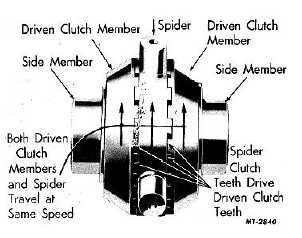
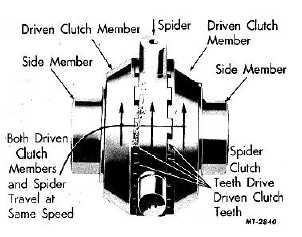
Fig. 37 Straight Forward Driving
Straight Rearward Driving
When driving a vehicle in a straight rearward
direction, both driven clutch members are held in full
engagement with the spider and center cam as
described for straight forward driving. However, in this
case, the spider rotates in the reverse direction and
shifts the driving force to the opposite set of driving
faces on the mating clutch teeth. Again we have the
assembly operating as a unit with each wheel being
forced to rotate at ring gear speed.
Right-Hand Turn Forward Direction
When making a turn, differential action is
required in order to permit the outside wheel to travel a
greater distance, and faster, than the inside wheel.
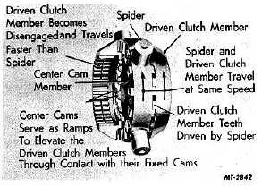
Fig. 38. Right-Hand Turn--Forward Direction
A conventional bevel gear type differential
permits the outside wheel to turn faster than
ring gear speed while the inside wheel turns slower than
ring gear speed. The NoSPIN differential allows either
wheel to turn faster than the ring gear speed but does
not permit either wheel to turn slower than the ring gear
speed when power is applied.
When negotiating a right-hand turn in a forward
direction, the right-hand driven clutch member remains
fully engaged with the spider clutch teeth and the
corresponding cams, Fig. 38.
The driving clutch teeth of the spider transmit
the driving force to the driven clutch member, which in
turn drives the right-hand (inside) wheel constantly at
right gear speed, thus propelling the vehicle. The left-
hand (outside) wheel covers a greater arc than the right-
hand (inside) wheel and driven by the traction of the
road, must turn faster than ring gear speed. Likewise,
the left-hand driven clutch member must turn faster than
the spider. In other words, it permits differences in
wheel speeds or differential action. Fig. 39 illustrates
how this is accomplished.
Fig. 39. Forward Right-Hand Turn (Cross
Sectional View)
The right-hand row of cams on the center cam
member are meshed securely with the cams on the
right-hand driven clutch member. With the center cam
thus locked in this position so that it cannot rotate with
respect to the spider, its cams on the left-hand side
serve as ramps upon which the mating cams on the
lefthand driven clutch member can rise, enabling that
driven clutch member to disengage from the spider.
The ramps on the center cam are high enough to permit
the clutch teeth on the driven clutch member to clear the
teeth on the spider and when the crest of the ramp is
passed, the teeth of the driven clutch member are
forced back by spring pressure into full engagement with
the clutch teeth of the spider.
CTS-2095S - Chapter II - Page 4
PRINTED IN UNITED STATES OF AMERICA
|


