|
| |
TRUCK SERVICE MANUAL
TM 5-4210-230-14&P-1
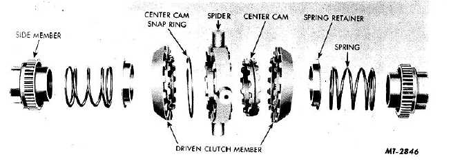
Fig. 34 Internal Spring Design differential Locking Unit (Exploded View)
DESCRIPTION
The NoSPIN differential (Figs. 34 and 35)
provides equal amounts of drive line torque to each rear
driving wheel and also permits differential action for
turning corners.
This differential also provides greater operating
flexibility than a conventional differential, because the
locking type differential overcomes wheel spinning when
required to operate in mud, sand, snow and on ice or
wet roads. The unit is installed in the differential case in
place of the conventional gears, pinion and spider. The
action of the unit is the same for both drive and coast
loads and forward and reverse driving.
CONSTRUCTION
Two types of NoSPIN differentials have been
used on IH vehicles; they are (a) Internal Spring Design,
Fig. 34, and (b) External Spring Design, Fig. 35.
The difference in the two units is explained in
the text; however, the disassembly will cover the
internal design locking unit.
The differential locking unit consists of several
parts, all assembled around the spider.
Spider and Center Cam Assembly
This assembly consists of the spider, center
cam and spider snap ring. The spider has four trunnions
projecting radially from a center ring on each side of
which are located fixed driving clutch teeth. These teeth
vary in number, depending on the size and model of
differential. The internal diameter of the spider is
uniform. Into it is mounted the center cam. This cam is
held in position with a centrally mounted snap ring,
which permits the center cam to be rotated within the
spider but prevents lateral movement. The center cam
is symmetric, having the same number of cam lifts on
each side as there are clutch teeth on the spider. These
lifts or "cams" have uniform contours with rounded
surfaces that provide anti-friction ramps for disengaging
the driven clutch members.
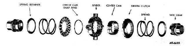
Fig. 35. External Spring Design Differential Locking Unit (Exploded View)
CTS-2095S - Chapter II - Page 2
PRINTED IN UNITED STATES OF AMERICA
|