|
| |
TRUCK SERVICE MANUAL
TM 5-4210-230-14&P-1
SET GEAR LASH
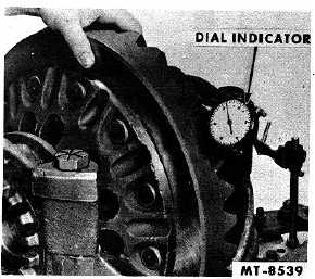
A special effort should be made to set the
backlash between pinion and ring gear to the same
amount as was originally built into them, 0.1-0.15 mm
(.004 to .006) on small gears or 0.15-0.2 mm (.006 to
.012) on larger gears. Generally the amount of backlash
is stamped or etched on the ring gear, Fig. 25. When
installing new gears, backlash is measured with a dial
indicator mounted on differential housing, as in Fig. 29.
To adjust the backlash, move the ring gear toward or
away from the pinion by means of the differential
bearing adjusting nuts.
Fig. 29 Using Dial Indicator to Set Correct
Backlash
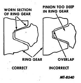
Fig. 30 Right and Wrong Adjustment of Ring Gear and
Pinion When Worn Gears Are Reinstalled
When original gear and pinion sets are being
reinstalled, the wear pattern of the gear teeth must be
considered in the backlash adjustment. Gears that have
been in service for long periods form running contacts
which should not be greatly changed. If, in checking
backlash, the amount measured is in excess of the
amount shown on the ring gear, the lash may be
reduced only in the amount that will avoid overlap of the
worn tooth section, Fig. 30. A slight overlap at the worn
section will cause gear operation to be noisy and rough.
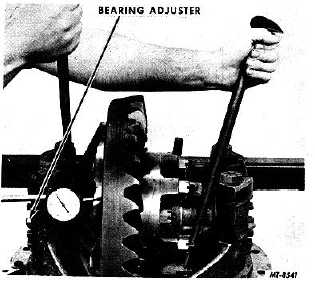
PRELOAD DIFFERENTIAL BEARINGS
After the ring gear has been adjusted for
position, another adjustment, the differential bearing
preload, is also accomplished by these same differential
bearing adjusting nuts. To set the preload, mount dial
indicator at side of ring gear, Fig. 31, and continue the
adjustment as follows:
Fig. 31 Adjusting Differential Bearing Preload
1. With the side bearing cap capscrews loosened
to permit bearing movement, loosen adjusting
nuts only enough to notice end play on
indicators.
2. Tighten adjusting nuts only enough to obtain .
000" end play reading on indicator. NOTE:
While gear is held in .000" end play and before
loading bearings, check gear for runout by
revolving ring gear. If runout exceeds 0.2 mm
(.008"), remove differential and check for cause.
3. Tighten both adjusting nuts from . 000" end
play to preload the differential bearings.
Tightening nuts one notch each usually gives
bearings the correct preload.
CTS-2095S - Chapter I - Page 13
PRINTED IN UNITED STATES OF AMERICA
|