|
| |
TRUCK SERVICE MANUAL
TM 5-4210-230-14&P-1
4. Tighten bearing cap capscrews or stud nuts to
specified torque.
5. Recheck gear lash to make certain that the lash
setting has not been changed during the
preloading operation.
6. Install adjusting nut locks.
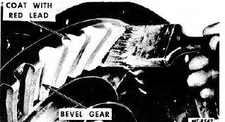
CHECK GEAR TOOTH CONTACT
The following instructions cover the paint
impression method of checking tooth contact and are
especially for the benefit of those not equipped with an
SE-1065 pinion setting gauge. The instructions may
also be used as a check on the adjustment obtained with
the gauge. By this method the mechanic temporarily
bolts up the pinion and cage to the differential carrier
and coats the drive gear teeth with oiled red lead, as in
Fig. 32. When the pinion is rotated, the red lead is
squeezed away by the contact of the teeth, leaving bare
areas the exact size, shape, and location of the
contacts. If these contacts are not acceptable, shims
must be added to or taken from the shim pack located
between the pinion cage flange and differential carrier
housing. In this manner, a satisfactory adjustment is
accomplished. Bear in mind that the accuracy of the
adjustment obtained with the paint impression method is
dependent upon the skill and experience of the
mechanic. It may be necessary to make several trials at
the right selection of shims to obtain the correct tooth
contact.
Fig. 32 Painting Gear Teeth for Obtaining
Tooth Contact Impressions
Sharper tooth contact impressions may be
obtained by applying a small amount of resistance to the
gear with a flat steel bar and using a wrench to rotate
the pinion. When making adjustments, check the drive
side of the ring gear teeth. Coast side contact should be
automatically correct when drive side contact is correct.
As a rule, coating about twelve teeth is sufficient for
checking purposes.
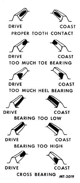
Fig. 33 Location, Size and Shape of Correct Tooth
Contacts
With adjustments properly made, a correct tooth
contact similar to that shown in Fig. 33 will be secured.
The area of contact starts near the toe of the gear and
extends about 62-1/2 percent of the tooth length. This
adjustment results in a quiet running gear and pinion
CTS-2095S - Chapter I - Page 14
PRINTED IN UNITED STATES OF AMERICA
|