|
| |
TRUCK SERVICE MANUAL
TM 5-4210-230-14&P-1
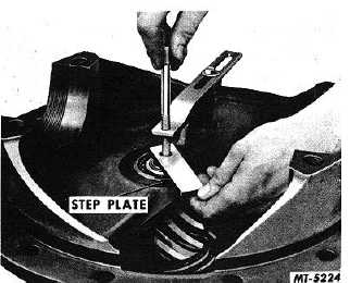
lugs on step plate straddle the bearing staking indentations on
end of pinion.
Fig. 27 Installing Step Plate
4.
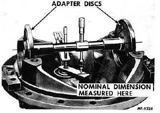
Mount assembled SE-1065 gauge in bearing bores of
carrier as shown in Fig. 28. Make certain that bearing bores
are clean and free of nicks and burrs. Adjust micrometer so it
is directly over end at a 90 degree angle to the step plate.
Take micrometer reading. Run the micrometer thimble down
to measure the distance between the center of the ring gear
and the step plate, or in the event of a spiral bevel type drive,
measure the distance to the face of the pinion itself. Make a
note of this measurement.
Fig. 28 Assembled Gauge in Position
5.
Locate pinion nominal dimension (cone center
specification) for the axle to be adjusted. On some
axles this dimension may be shown on the pinion.
Where this is not the case, it will be listed in the rear
axle specifications. Write down this specification.
6.
Also locate on pinion the etched marking which
indicates a variation from zero cone center. If a
minus figure, subtract from specified cone center,
and if a plus figure, add to specified cone center.
NOTE
The plus or minus variation marked on the
pinion
will
not
necessarily
show
small
variations such as -5, +3, or +7. On some
pinions the variation marking will range to
higher figures such as +56, +59 or perhaps
higher.
Results of calculation give the corrected cone center
or pinion nominal dimension to which the pinion must be set.
7.
Comparison of corrected cone center (6) with the
actual or measured cone center (4) indicates amount
of change necessary for pinion position.
8.
Remove gauge and install ring gear and differential
carrier in the differential housing.
9.
Adjust backlash according to marking on ring gear.
To further clarify the use of the SE1065 pinion setting
gauge, the dimensions from the same type of axle as used in
the aforementioned disassembly will be used as an example
of the calculation involved.
Data:
Rear Axle Model-RA20
Rear Axle Code-14020
SE-1065-9 Adapter Disc-N (2)
Pinion Nominal Dimension-2.9839
Pinion Marked-(-5)
Procedure:
(a) Take micrometer reading with gauge .................... 2.6239
Add .400 for thickness of step plate ............................ +.4000
Equals - Measured Nominal Dimension....................... 3.0239
(b) Record Pinion Nominal Dimension from Specifications or
stamped on pinion ................................ ...................... 2.9839
Subtract the Pinion Correction
(-5) ................................ ................................ ............. -.0050
Equals - Corrected Nominal Dimension or distance pinion
should measure from center of ring gear..................... 2.9789
(c) Subtract correct Nominal Dimension (b) from actual
measurement (a)
Equals - Amount pinion must be moved in .................. 0.0450
CTS-2095S-CHAPTER I-Page 12
PRINTED IN UNITED STATES OF AMERICA
|


