|
| |
TRUCK SERVICE MANUAL
TM 5-4210-230-14&P-1
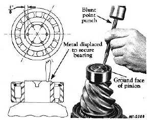
If the pinion radial or straddle bearing was removed
from the end of the pinion during the disassembly, the bearing
should be reinstalled at this time. Press the radial bearing
onto the end of pinion and stake with a blunt point punch, as
shown in Fig. 24, in six equidistant places. It is suggested
that for locating punch positions for staking, the end of the
pinion be painted with Prussian Blue and a circle be scribed
on end of pinion about 3.175 mm (1/8") in from the pinion
circumference. When staking the bearing, be careful to make
the depth of the indentations or stake points uniform.
Otherwise, the bearing might be damaged. Deep punch or
stake marks are not necessary. Apply the staking operation
at opposite sides of the pinion end until all stake points are
obtained.
NOTE
Smaller pinions having the straddle bearings
are staked in four places only. Where special
staking tools are available, they can be used;
otherwise, the use of a blunt or round-nose
punch is satisfactory.
Fig. 24 Staking Pinion Straddle Bearing
ESTABLISH NOMINAL DIMENSION
The pinion setting gauge (SE-1065) is a precision
gauge designed for locating the pinion as it meshes with the
ring gear to the correct nominal dimension in the shortest
possible time. A step plate and bracket, which are a part of
the set, are used whenever hypoid type gears are to be
adjusted. Essentially the pinion setting gauge is a direct
reading depth micrometer mounted in an arbor. The span of
the micrometer is 50-75 mm (2" to 3"), but extensions are
provided with the kit to increase the reach. Two sleeves which
hold adapter discs slip over the ends of the arbor. Adapter
discs are held on the sleeves by knurled nuts. When installed
in the differential case, the pinion setting gauge enables the
mechanic to measure the distance from the face or finished
end of the installed pinion to the centerline of the ring gear or
cross shaft. The measurement which the mechanic reads
should agree with the nominal dimension, which can be found
in the axle specifications, or which in some instances is
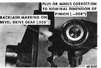
stamped or etched on the pinion itself. Usually there is a plus
or minus correction also stamped on the pinion, Fig. 25, and
this also must be figured in with the nominal dimension.
Fig. 25 Location of Pinion Setting Markings
The procedure for establishing the correct nominal
dimension by means of the pinion setting gauge is as follows:
1.
Install pinion, cage and bearing assembly in the
differential carrier.
2.
Attach the step plate clamp assembly to the carrier
flange and locate step plate clamp screw over the
center of the pinion as shown in Fig. 26.
Fig. 26 Locating Step Plate Clamp
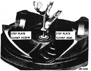
3.
Install step plate under clamp screw and tighten
screw to hold the step plate securely in position as
shown in Fig. 27. The step plate is necessary in
order to project the face of the pinion to where it can
be measured by the gauge which is on the centerline
of the ring gear.
NOTE
Be sure
CTS-2095S-CHAPTER I-Page 11
PRINTED IN UNITED STATES OF AMERICA
|