|
| |
TRUCK SERVICE MANUAL
TM 5-4210-230-14&P-1
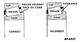
must be seated against the face of the bearing cone as shown
in Fig. 21. After the pinion bearing load is established, good
practice would be to check the ends of the bearing rollers to
see whether they are in contact with the face of the bearing
cone. Use a feeler gauge ribbon. There must be no
clearance at the ends of the rollers.
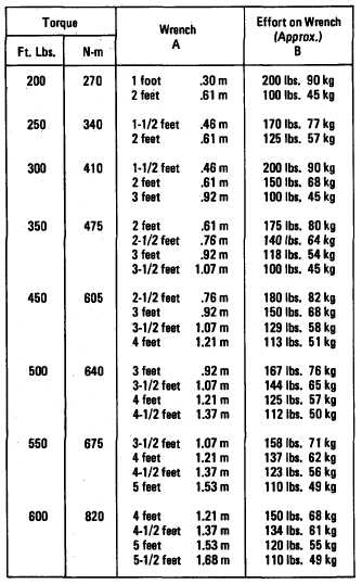
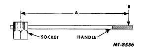
Fig. 20 Wrench Torque Chart and Diagram
Fig. 21 Roller Bearing When Correct Adjustment is Obtained.
(The rollers of the bearing must bear against the face of the
cone as shown. Rotation of the bearing during adjustment is
necessary to obtain this condition.)
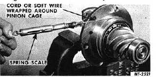
To measure the preload, wrap a strong cord or soft
wire about the pinion cage and attach end to the spring scale
as in Fig. 22. Read scale only while pinion cage is turning.
Compare this scale reading or pinion bearing preload with the
figure found in the rear axle specifications.
Fig. 22 Measuring Pinion Bearing Preload
When preload reading does not agree with the
specifications, the bearing load may be increased by installing
a thinner spacer or decreased by using a thicker spacer.
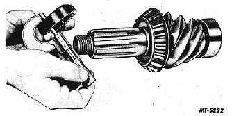
Determine spacer thickness with a micrometer, Fig. 23, and
make a new selection accordingly. Closer adjustment can be
made by working spacer to the desired thickness using emery
cloth on a flat surface. Wash spacer clean of emery cuttings
before installing on pinion
Fig. 23 Measuring Spacer Thickness
CTS-2095S-CHAPTER I-Page 10
PRINTED IN UNITED STATES OF AMERICA
|

