|
| |
TRUCK SERVICE MANUAL
TM 5-4210-230-14&P-1
AXLES-FRONT
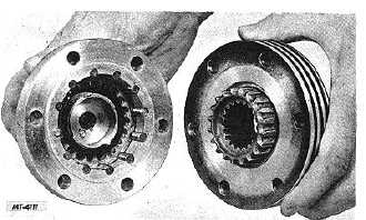
Fig. 19. Clutch Body and Hub Body Properly Assembled
(Manual Type)
Fig. 19 shows the manual type clutch body and hub
body ready for assembly on the vehicle.
Hub Body (Lock-O-Matic)
Install thrust washer (13) in hub body (16). Place the
Spirolox lock ring (15) in its groove in the hub body (6) to hold
the thrust washer in position, Fig. 18.
Position new friction shoes (4) into roller cage (9).
Secure friction shoes by installing spring (3) as illustrated in
Fig. 15. Install Spirolox lock ring (10) into end (opposite
friction shoes) of roller cage (9).
Insert axle shaft hub (11) into roller cage (9) against
Spirolox spring (10). See Fig. 16. NOTE: Points on axle shaft
hub must be aligned with grooves in friction shoes to permit
entry. Install Spirolox lock ring (12) into second groove on
axle shaft hub (11). See Fig. 15.
Slip the centering spring (8) into the groove in the
back side of the axle shaft hub, Fig. 14. NOTE: The two ends
of the spring go into the slot in the cage which is longer than
the rest. Place a small amount of lightweight chassis
lubricant into all the slots in the cage and into the bore of the
hub body.
Hold the hub and cage assembly with the clutch end
up and insert the ten rollers (7) into the cage slots. Slip axle
shaft hub and cage assembly into hub body (6) from back
side. Install lock ring (14) into remaining groove in axle shaft
hub (11) using lock ring pliers.
Clutch Body (Lock-O-Matic)
The reassembly instructions for the Lock-O-Matic
clutch body are the same as for the manual type. See
"REASSEMBLY-Clutch Body (Manual Type).”
Fig. 20. Clutch Body and Hub Body Properly Assembled
(Lock-O-Matic)
Fig. 20. illustrates the Lock-O-Matic clutch body and
hub body ready to be assembled on the vehicle.
ADJUSTMENT
No adjustment of any kind is required on the manual
or Lock-O-Matic locking hubs except for the positioning of the
clutch screw during reassembly. See "REASSEMBLY--Clutch
Body."
LUBRICATION
Both locking hubs should be lubricated at assembly
with a thin coat of Lithium 12-Hydroxy Stearate EP grease.
NOTE: Do not pack hub full of grease.
CTS-2209-H Page 9
PRINTED IN UNITED STATES OF AMERICA
|