|
| |
TRUCK SERVICE MANUAL
TM 5-4210-230-14&P-1
AXLES-FRONT
CHAPTER II
DISASSEMBLY:
1.
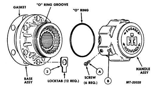
With handle in disengage position, remove handle
assembly by removing the three screws "A". Do not
remove the three screws "B".
2.
If screws "B" are removed, misalignment could occur
on reassembly causing damage to cam. There is no
reason to ever remove screws "B".
3.
Remove and retain retaining ring on axle.
4.
Remove base assembly, by removing six bolts.
5.
If locktabs were used, the tabs must be bent out of
the way of the bolt head.
6.
Clean gasket surfaces thoroughly.
7.
Wipe the axle spline clean and lubricate.
REASSEMBLY:
1.
Install the base assembly with new gasket in place,
to the vehicle hub.
2.
Secure base assembly to vehicle with bolts and new
lock tabs.
3.
The tab on the locktab is to be bent up against flat on
head of bolt to insure against loosening.
4.
Install retaining ring on axle shaft.
5.
Install new "O" ring into groove on base assembly.
6.
Apply thin film of grease to "O" ring, prior to installing
handle assembly.
7.
Place the handle assembly in position.
8.
With the splines of the sliding gear aligned with the
splines within base, push the handle assembly on the
base.
9.
Using hand pressure, compress the spring enough to
allow the screw holes for screws "A" to line up with
the groove in base.
10.
Insert three new screws "A". DO NOT FORCE.
Screws must enter and screw into place freely.
Fig. 1.
CTS-2209-P Page 1
PRINTED IN UNITED STATES OF AMERICA
|