|
| |
TRUCK SERVICE MANUAL
TM 5-4210-230-14&P-1
AXLES-FRONT
Remove the friction shoe spring (3) as shown in Fig.
17. Friction shoes (4) may now be lifted out of roller cage (9).
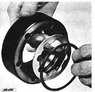
Fig. 18. Removing Spirolox Lock Ring and Thrust Washer
Remove the Spirolox lock ring (15) and thrust washer (13)
from the hub body (6). See Fig. 18.
Clutch Body (Lock-O-Matic)
Disassembly of the Lock-O-Matic clutch body is
identical to that of the manual type. Therefore, refer to the
disassembly procedure outlined under "Clutch Body (Manual
Type)" when disassembling the Lock-O-Matic hub.
CLEANING, INSPECTION AND REPAIR
Thoroughly wash all parts of the locking hub using a
good cleaning solvent. Dry all parts with compressed air or a
clean, lint-free cloth.
Inspect all parts for wear or damage. Check needle
bearings, rollers, axle shaft hub and hub body for pits or
cracks. Splines of axle shaft hub and clutch ring should be a
free sliding fit. If splines are worn or damaged, these parts
should be replaced. Use all new O-ring seals and gaskets
during reassembly.
REASSEMBLY
Hub Body (Manual Type)
If hub body needle bearing has been removed, install
new bearing being careful not to damage it.
Place axle shaft hub (4) into hub body (3) as shown
in Fig. 7. Secure axle shaft hub (4) in body (3) by installing
snap ring (1) in groove in end of axle shaft hub.
Clutch Body (Manual Type)
Apply a small amount of chassis lubricant on the
bearing side and in the grooves of the control assembly (16).
Install new O-ring seals (10 and 17) on control assembly (16).
If the hub has a seal groove, position the split towards the
outside of dial. Place disc (9) on inside (clutch side) of clutch
body (13). See Fig. 10.
Assemble clutch screw (8) into clutch ring (6) from
back side (Fig.8). Be certain clutch screw works freely. If it is
sticky in any position, tap lightly from the back side. Drop in
clutch ring and screw assembly. NOTE: Clutch screw (8)
should be flush with the back edge of clutch ring (6). Insert
the twelve drive pins (11). Try clutch ring for a free sliding fit
on drive pins. If it doesn't move freely from top to bottom, lift
out clutch ring and screw assembly and turn it to another
position. If it still does not move freely, it should be removed
and the clutch ring (6), clutch body (13) and drive pins (11)
examined for damage.
Apply a light grade chassis lubricant to the inside
face of the clutch body (13) and disc (9) from the front side of
the clutch body./ NOTE: Hold hand over drive pins to prevent
their falling out.
Position control assembly (16) with dowel pin (20)
into face of clutch body (13) so the arrow stops on the dot
marked "FREE." Install and tighten the flat head screw (7)
into the control assembly (16). NOTE: If screw (7) was
damaged during disassembly, it should be replaced.
To check clutch screw setting, turn control assembly
(16) from "LOCK" to "FREE" position and back several times.
Control assembly should "snap" into both positions. In
"FREE" position clutch ring (6) should just clear bottom of
clutch body (13).
NOTE: If clutch ring is set too far above
bottom of clutch body when set in the "FREE"
position, axle shaft hub (4) will rub face of
clutch ring.
Stake dowel pin (20) and flat head screw (7).
Turn control assembly (16) to "FREE" position and
apply a thin coating of light grade chassis lubricant around the
clutch screw (8) and drive pins (11).
CTS-2209-H Page 8
PRINTED IN UNITED STATES OF AMERICA
|