|
| |
TRUCK SERVICE MANUAL
TM 5-4210-230-14&P-1
AXLES-FRONT
Hub Body (Lock-O-Matic)
NOTE: All key numbers used in "DISASSEMBLY" and
"REASSEMBLY" of the Lock-O-Matic hub refer to Fig. 12.
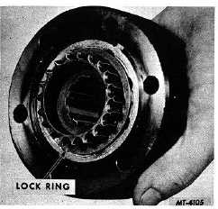
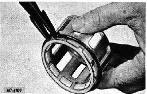
Remove lock ring (14) retaining axle shaft hub (11) into hub
body (6). See Fig. 13. Pull axle shaft hub (11) and roller
cage assembly (9) out of hub body noting side of hub from
which gear teeth extend.
Fig. 13. Hub Body
Remove the 10 rollers (7) from the roller cage (9). Take out
centering spring (8).
See Fig. 14.
Fig. 14. Removing Centering Spring and Rollers
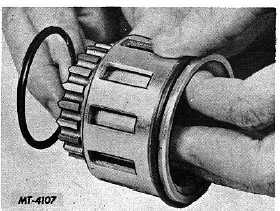
Remove Spirolox lock ring (12) located in second groove on
axle shaft hub (11). See Fig. 15. This permits the axle shaft
hub to be separated from the roller cage.
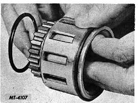
Pull the axle shaft hub (11) out of the roller cage (9) in the
direction as illustrated in Fig. 16.
NOTE: The corner points of the axle shaft hub must be
aligned with the grooves in the friction shoes to
permit removal of the hub. Remove Spirolox locking
ring (10) located in roller cage in end opposite friction
shoes (4).
Fig. 15. Removing Spirolox Lock Ring
Fig. 16. Separating Axle Shaft Hub from Roller Cage
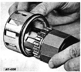
Fig. 17. Removing Friction Shoes and Spring
CTS-2209-H Page 7
PRINTED IN UNITED STATES OF AMERICA
|