|
| |
TM 5-4210-230-14&P-1
TRUCK SERVICE MANUAL
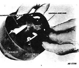
the two elongated openings in cage aligned with
opposite teeth of outer race bell (Fig. 12). Lift cage and
inner race from outer race bell.
Fig. 12 Removing Cage and Inner Race
4.
To separate inner race from cage turn inner race at
right angle to cage, align notched tooth of inner race
with elongated opening in cage, and roll inner race out
of cage.
Cleaning and Inspection
Remove all dirt, old lubricant and gasket material from
all components. Immerse in cleaning solvent and use a stiff
brush if necessary. Bearings should be cleaned separately in
clean solvent and special efforts taken to protect their finely
machined surfaces. If compressed air is used for drying, do
not spin bearings while drying.
Examine all bearings for roughness, damage or wear
by rotating each bearing slowly in the hand. If in doubt as to
bearing condition, replace.
Inspect axle shaft and universal joint assembly for
seizure, broken or chipped balls, broken splines or other
damage
Inspect spindle bushing for out of round condition
caused by wear or corrosion, scoring or roughness in spots.
Inspect axle shaft oil seal for evidence of wear or
damage.
Inspect for evidence of wear due to improper drive
flange shim size. Wear on the interior surface of ball end of
axle housing and on edge of ball joint bell housing indicates
the use of too thin a shim, allowing contact between the two.
If shim is too thick, the spindle bushing will show excessive
wear.
Oil Seal and Bearing Replacement
1.
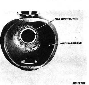
To replace axle shaft oil seal (Fig. 13) pry out old seal
from bore of axle housing and discard. Install new
seal. Seal must contact counterbore.
Fig. 13 Axle Shaft Oil Seal
2.
To remove upper and lower trunnion bearing cups,
drive cups out of axle housing bores with a driver and
brass drift inserted through the opposite bore (Fig. 14).
When installing new trunnion bearing cups care should
be taken not to nick or scar bearing mating surface of
cup.
Cups and bearings should be replaced as a matched
set.
3.
To remove spindle bushing (Fig. 15) insert puller in
bushing bore and extract old bushing and discard.
Install new bushing in bore. Bushing must contact
counter bore.
CTS-2658S Page 16
PRINTED IN UNITED STATES OF AMERICA
|


