|
| |
TRUCK SERVICE MANUAL
TM 5-4210-230-14&P-1
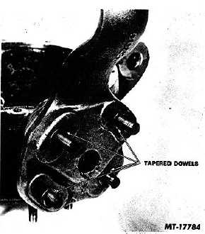
Fig. 8 Tapered Dowels
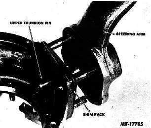
Fig. 9 Steering Arm Removal
It is not necessary to remove the upper trunnion pin
upon trunnion housing disassembly. However, if so
desired the upper trunnion pin may be tapped from its
bore by working through the trunnion housing rear
opening.
Axle Shaft and Universal Joint Disassembly
1.
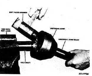
Place axle shaft in a vise equipped with soft jaws.
Grasp shaft end of universal
joint and pull while rapping back side of joint with a soft
faced hammer (see Fig. 10).
Fig. 10 Axle Shaft and Universal Joint Disassembly
Remove lock ring from axle shaft end and discard. A
new lock ring should always be used on reassembly.
2.
Place universal joint in a vise equipped with soft jaws
with outer race bell upward.
Tilt inner race in outer race until one ball can be
removed, continue this procedure until all balls are
removed. A soft faced hammer may be used to aid
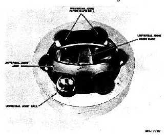
inner race movement. See Fig. 11.
Fig. 11 Removing Universal Joint Balls
3.
Roll universal joint cage at a right angle to universal
joint outer race bell with
CTS-2658S Page 15
PRINTED IN UNITED STATES OF AMERICA
|


