|
| |
TRUCK SERVICE MANUAL
TM 5-4210-230-14&P-1
19.
Run micrometer thimble down to measure distance
between center of ring gear and step plate. Make a note of
this reading along with the nominal dimension given in
"SPECIFICATIONS". Locate on pinion the etched marking
which indicates variation from zero cone setting. If it is a
minus figure, subtract it from specified dimension, and if a
plus figure, add it to specified dimension. Results of
calculation
will
provide
the
corrected
pinion
nominal
dimension to which pinion must be set. Comparison of
corrected nominal dimension with the actual or measured
dimension indicates amount of change necessary for correct
pinion position. It may be necessary to add or remove shims
between cage and differential carrier to provide correct pinion
nominal dimension.
20.
Remove gauge and prepare to install ring gear and
differential carrier in differential housing.
21.
If drive gear was removed from case, rivet gear to case
flanged half.
When reinstalling ring gear, it is suggested that
Riveting Jig SE-1575 be used. This special tool is
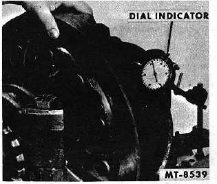
designed for use with either hydraulic or mechanical
press equipment. Rivet pressures for ring gear
installation should be in accordance with those given in
"SPECIFICATIONS".
22.
Apply axle lubricant to differential case inner walls and
all other component parts.
23.
Place thrust washer (25) and side gear (26) in flanged
half of case together with spider (27), pinion gears (28) and
thrust washers (29).
24.
Install opposite side gear and thrust washer in
differential case plain half (24).
25.
Align the match marks and join the two differential case
halves. Draw assembly together with four equally spaced
bolts (23) and nuts (33).
26.
Check assembly for free rotation of side gears and
pinions and if satisfactory, install remaining differential case
bolts. Tighten to torque specified in "TORQUE CHART".
27.
Differential bearings (22) are installed by pressing them
squarely onto differential case halves.
28.
Prelubricate differential bearings with axle lube and
place bearing cups (21) over
bearings. Attach chain sling to differential assembly and
install in carrier.
29.
Place bearing adjusters (14) in carrier and turn hand
tight against bearing cups (21).
30.
Observe match marks on bearing caps and install caps
onto legs of differential carrier (20).
31.
Install bearing cap bolts(17) and washers. Tighten to
specified torque. (See "TORQUE CHART".)
32.
Tighten bearing adjusters (14) alternately until all end
play is eliminated. Rotate differential while tightening.
Gear Lash
33.
A special effort should be made to set the backlash
between pinion and ring gear to the same amount as was
originally built into them .15-.30 mm (.006" to .012").
Generally the amount of backlash is stamped or etched on the
ring gear. When installing new gears, backlash is measured
with a dial indicator mounted on differential housing (Fig. 16).
To adjust the backlash move the ring gear toward or away
from the pinion. This is done by backing off one adjusting
ring and advancing the opposite ring the same amount.
Fig. 16 Setting Correct Backlash
34.
When original gear and pinion sets are being
reinstalled, the wear pattern of the gear teeth must be
considered in the backlash adjustment. Gears that have been
in service for long periods form running contacts which should
not be greatly changed. If, in
CTS-2658S Page 9
PRINTED IN UNITED STATES OF AMERICA
|