|
| |
TRUCK SERVICE MANUAL
TM 5-4210-230-14&P-1
12.
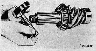
Wash spacer clean of emery cuttings before installing
on pinion.
Fig. 12 Measuring Spacer Thickness
13.
After pinion bearing preload is established good
practice would be to check bearing roller ends to see whether
they are in contact with bearing cone face. Use a feeler
gauge ribbon. There must be no clearance at ends of rollers
(Fig. 11).
Check pinion end nut for correct torque and install
cotter pin.
Pinion Nominal Dimension
To establish pinion nominal dimension which is the
distance from the face or finished end of the installed pinion to
the centerline of the ring gear or cross shaft, proceed as
follows.
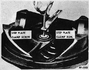
Fig. 13 Locating Step Plate Clamp
14.
Install pinion, cage and bearing assembly in differential
carrier. Obtain step plate clamp assembly from SE-1065
Pinion Setting Gauge set and attach it to differential carrier
flange, locating step plate clamp screw over center of pinion
(Fig. 13).
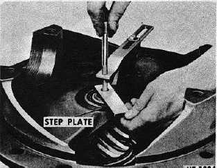
15.
Install step plate under clamp screw and tighten screw
to hold step plate securely in position (Fig. 14).
Fig. 14 Installing Step Plate
16.
The step plate is necessary to project the face of the
pinion where it can be measured by the gauge which is on the
centerline of the drive gear.
Be certain lugs on step plate straddle the bearing
staking indentations on end of pinion.
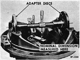
17.
Mount assembled SE-1065 gauge in bearing bores of
carrier (Fig. 15). See "SPECIFICATIONS" for correct disc
size.
Fig. 15 Assembled Gauge in Position
18.
Make certain that bearing bores are clean and free of
nicks and burrs. Adjust micrometer so it is directly over end
at a 90 degree angle to step plate.
CTS-2658S Page 8
PRINTED IN UNITED STATES OF AMERICA
|