|
| |
TM 5-4210-230-14&P-1
TRUCK SERVICE MANUAL
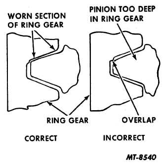
checking backlash, the amount measured is in excess of the
amount shown on the ring gear, the lash may be reduced only
in the amount that will avoid overlap of the worn tooth section
(Fig, 17). A slight overlap at the worn section will cause gear
operation to be noisy and rough.
Fig. 17 Correct and Incorrect Lash Adjustment where worn
Gears are Reinstalled
Differential Bearing Preload
35.
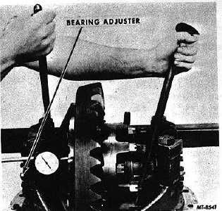
To set the bearing preload, mount dial indicator at side
of ring gear (Fig. 18). With the bearing capscrews loosened
to permit bearing movement, loosen adjusting nuts only
enough to notice end play on indicator.
36.
While gear is held in .000" end play and before loading
bearings, check gear for runout by revolving ring gear. If
runout exceeds 20 mm (.008"), remove differential and check
for cause. 37. Tighten both adjusting nuts from .000" end
play
to
preload
the
differential
bearings
(see
"SPECIFICATIONS").
38.
Tighten bearing cap, capscrews or stud nuts to
specified torque (see "TORQUE CHART").
39.
Recheck gear lash to make certain that the lash setting
has not been changed.
Fig. 18 Adjusting Bearing Preload
40.
Install adjusting rings locks and cotter pins.
Gear Tooth Contact
41.
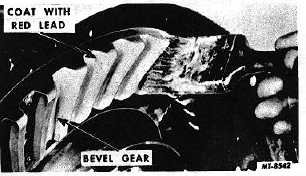
Apply oiled red lead lightly to the hypoid gear teeth
(Fig. 19).
Fig. 19 Painting Gear Teeth for Obtaining Tooth Contact
Impressions
42.
When the pinion is rotated, the red lead is squeezed
away by the contact of the teeth, leaving bare areas the exact
size, shape and location of the contacts (Fig. 20).
43.
Sharper impressions may be obtained by applying a
small amount of resistance to the gear with a flat steel bar
and using a wrench to rotate the pinion. When making
adjustments, check the drive side of the gear teeth. Coast side
should be correct when drive side is correct. Generally,
coating approximately
CTS-2658S Page 10
PRINTED IN UNITED STATES OF AMERICA
|