|
| |
TRUCK SERVICE MANUAL
TM 5-4210-230-14&P-1
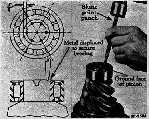
Fig. 9 Staking Pinion Straddle Bearing
It is suggested that for locating punch' positions
for staking, the end of the pinion be painted with
Prussian Blue and a circle be scribed on end of pinion
about 3.17 mm (1/8") in from the pinion circumference.
When staking the bearings be careful to make the
depth of the indentations or stake points uniform,
otherwise bearing may be damaged. Deep punch or
stake marks are not necessary. Apply the staking
operation at opposite sides of the pinion end until all
stake points are obtained. Where special staking tools
are available, they can be used, otherwise the use of a
blunt or round nosed punch is satisfactory.
3.
If bearing cups (7) have been replaced, press new cups
firmly against shoulders of pinion cage (10).
4.
Prelubricate the bearings with gear lubricant.
5.
Position spacer (8) on pinion shaft and against rear
thrust bearing.
6.
Insert pinion and rear thrust bearing (6) in pinion cage.
7.
Mount pinion and cage in arbor press and place pre-
lubricated front thrust bearing (6) on pinion shaft. Press
bearing firmly and squarely against spacer.
Pinion Bearing Preload
Pinion
bearing
preload
is
established
by
selecting the correct size spacer (8) located between
the two pinion thrust bearings and tightening pinion end
nut to the specified torque (see "TORQUE CHART").
8.
Temporarily assembly the pinion, cage and
flange assembly, less oil seal and retainer. Clamp the
assembly in a vise to hold the companion flange. Tighten end
nut to specified torque.
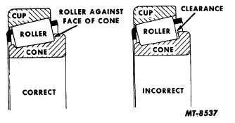
9.
The pinion cage should be rotated while tightening the
pinion to seat and align the bearings. Rotation of the pinion is
important. Otherwise a false condition of bearing load could
exist. The bearing rollers must be seated against the face of
the bearing cone (Fig. 10).
Fig. 10 Pinion Bearing Roller Position
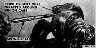
10.
To measure bearing preload, wrap a strong cord or soft
wire about the pinion cage and attach end to spring scale (Fig.
11). Read scale only while cage is rotating. Compare this
scale reading with the figure shown in "SPECIFICATIONS".
Fig. 11 Measuring Pinion Bearing Preload
11.
When
preload
does
not
agree
with
"SPECIFICATIONS", bearing load may be increased by
installing a thinner spacer or decreased by using a thicker
spacer. Determine spacer thickness using a micrometer (Fig.
12) and make a new selection accordingly. Closer adjustment
may be obtained by working spacer to desired thickness,
using emery cloth on a flat surface.
CTS-2658S Page 7
PRINTED IN UNITED STATES OF AMERICA
|