|
| |
TRUCK SERVICE MANUAL
TM 5-4210-230-14&P-1
9.
Remove self-locking nuts from differential case bolts
and separate the case halves.
10.
Remove differential spider, spider gears, side gears
and thrust washers from differential case halves.
11.
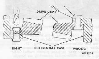
If necessary to remove drive gear, carefully center
punch each rivet head on drive gear side and drill through the
rivet head with a drill .79 mm (1/32") smaller than rivet body
(Fig. 3). Use a punch to press out remaining portion of rivet.
Never use chisel to cut off rivet heads or damage to case
might result.
Fig. 3 Drive Gear Rivet Removal
12.
Take out pinion cage bolts which hold the cage to
differential carrier.
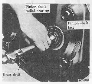
13.
Obtain a brass drift and hammer and strike against
rear face of pinion shaft (Fig. 4) to start pinion and cage out
of carrier.
Fig. 4 Loosening Pinion and Cage from Carrier
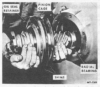
14.
Remove the pinion and cage assembly from the carrier
(Fig, 5). Because of the weight of the pinion and cage
assembly make sure that parts are secured safely while
removing. Pinion and cage might be damaged if allowed to
fall.
Fig. 5 Removing Pinion and Cage Assembly
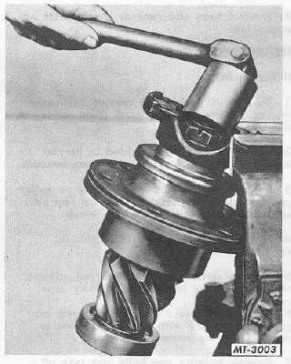
Fig. 6 Removing Pinion End Nut
15.
Mount the pinion and cage assembly in a heavy duty
vise and remove the pinion end nut as shown in Fig. 6.
CTS-2658 Page 4
PRINTED IN UNITED STATES OF AMERICA
|