|
| |
TRUCK SERVICE MANUAL
TM 5-4210-230-14&P-1
DESCRIPTION
The axle covered in this manual is a front driving unit
incorporating hypoid gears and spherical steering knuckles.
Driving torque from the axle shaft to the wheels is transmitted
by a drive flange bolted to the axle shaft.
Complete Overhaul
1.
Jack up truck until load is removed from the springs
and place floor jack under frame to safely secure truck weight
off axle.
2.
Drain lubricant from housing.
3.
Disconnect brakes.
4.
Disconnect drag link from ball stud bracket .
5.
Disconnect propeller shaft from pinion shaft yoke.
6.
Support axle on portable floor jack and remove spring
bolts.
7.
Roll axle out from truck and position on stationary floor
jacks.
8.
Remove tires and rims or disc wheels as appropriate.
DISASSEMBLY
Differential
1.
To remove differential carrier from axle housing remove
mounting nuts from carrier to axle housing flange.
2.
Use puller screws provided in carrier mounting flange
to start carrier from housing.
3.
Support weight of carrier safely on roller type floor jack
or portable floor lift and roll jack and carrier out from under
truck.
4.
Mount differential carrier in rebuild stand .
5.
Remove cotter pins from bearing adjuster locks and
remove locks from bearing caps.
6.
Match mark one differential bearing cap and leg of
carrier with punch or chisel to identify each for correct
reassembly.
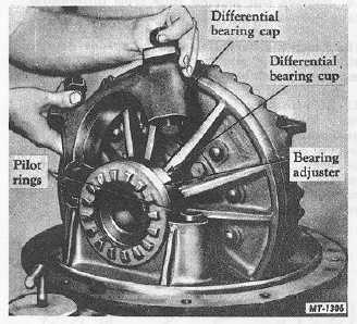
7.
Remove bearing cap bolts and take off the bearing
caps and bearing adjusters (Fig. 1).
Fig. 1 Removing Differential Bearing Caps
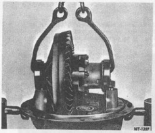
Attach chain sling from overhead hoist and lift
differential and drive gear assembly from the differential
carrier (Fig. 2). Tilt either the carrier or differential assembly
to allow drive gear to pass pinion radial bearing. Place
differential assembly on bench.
Fig. 2 Lifting Differential from Carrier
8.
Match mark differential case halves with a punch or
chisel to assure correct alignment on reassembling.
CTS-2658S Page 3
PRINTED IN UNITED STATES OF AMERICA
|