|
| |
TRUCK SERVICE MANUAL
TM 5-4210-230-14&P-1
16.
Drive the pinion assembly from the companion flange
with a soft hammer. Do not allow pinion assembly to fall.
17.
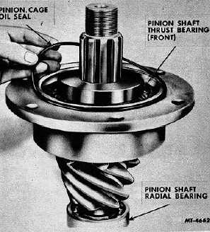
Remove pinion cage "O" ring type seal (Fig. 7).
18.
Tap pinion from cage and remove forward thrust
bearing.
19.
Remove the thrust bearing spacer from the pinion
shaft.
20.
If it is necessary to remove the rear thrust bearing or
the radial bearing from the pinion shaft; remove these
bearings with a suitable puller.
Fig. 7 Removing Pinion Cage Oil Seal
CLEANING, INSPECTION AND REPAIR
Remove all dirt, old lubricant and gasket material from
components of the front axle. Immerse in cleaning solvent and
use a stiff brush if necessary. Bearings should be cleaned
separately in clean solvent and special efforts taken to protect
their finely machined surfaces. If compressed air is used for
drying, do not spin bearings while drying.
Never use anything but brake fluid to clean
hydraulic brake cylinders.
Examine all bearings for roughness, damage to wear
by rotating each bearing
slowly in the hand. If in doubt as to bearing condition,
replace. Ring gear, drive pinion, differential pinions and any
other gears should be checked for damaged teeth, worn
spots, or distortion. Inspect differential case assembly for
cracks, damage or distortion. Make sure splined ends of axle
shafts are neither twisted or cracked. Shim packs should be
of uniform thickness. Discard thrust washers and obtain new
even when only slight wear is indicated. Always use new
gaskets. Hex nuts and capscrews with rounded corners, all
lockwashers, seals, pins and bushings should be replaced.
REASSEMBLY
Differential
The principal adjustments made on the differential
carrier assembly are devised for establishing the proper gear
tooth contact and thereby obtaining a long wearing, quiet
running front axle. Fundamentally, there are five adjustments
to be covered and these are accomplished as the differential
carrier assembly is assembled. To emphasize their
importance these five steps or adjustments are listed here as
well as in the actual assembly procedure. These adjustments
are:
1.
Preload the pinion bearings.
2.
Establish the pinion nominal dimension.
3.
Set gear lash.
4.
Preload the differential bearings.
5.
Check the gear tooth contact.
Refer to the exploded view (Fig. 8) and reassembly
differential carrier as follows.
1.
Press rear thrust bearings (6) firmly against shoulder of
pinion shaft (12).
2.
Press radial bearing (13) on stub end of pinion shaft
(12) and against pinion. Stake face of pinion evenly in six
places to secure radial bearing in place (Fig. 9).
CTS-2658S Page 5
PRINTED IN UNITED STATES OF AMERICA
|

