|
| |
TRUCK SERVICE MANUAL
TM 5-4210-230-14&P-1
WHEELS, RIMS, TIRES
2.
Continue "Walking" side-ring into place (Fig. 41). ,
Fig. 41
3. Check to insure that side-ring is fully seated in gutter as
shown in Figure 42.
Fig. 42
4.
Place tire assembly into safety cage and inflate to a
maximum of 10 psi using an extension hose with gauge
and clip-on chuck. Check side-ring by lightly tapping
with mallet to insure proper engagement. Inspect to
insure proper seating of beads. Completely deflate tire
to prevent tube from buckling. Reinflate to
recommended pressure.
THREE-PIECE FLAT BASE
Dismounting:
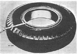
1.
Remove valve core and completely deflate the tire or
both tires if working on duals before removing the tire
and rim assembly from the truck. Remove tire
assembly from truck and place on floor with the side-
ring up. Insert
tapered end of rim tool into depression in lock ring, or
between rings, and press down on side ring to free bead.
Continue around tire until the bead is completely freed from
the bead seat (Fig. 43).
Fig. 43
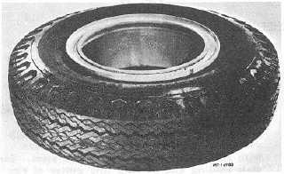
2.
Insert rim tool into removing notch, near split in the ring
and push downward to remove lock-ring from rim
gutter. A second rim tool may be helpful to aid in
removal (Fig. 44).
Fig. 44
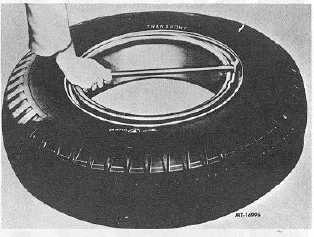
3.
Insert rim tool between lock-ring and sidering. Press
down to pry ring up and continue around rim until lock-
ring is free (Fig. 45). Remove lock and side-rings from
rim. Turn assembly over, unseat second tire bead,
stand tire up and remove rim base.
CTS-2032N Page 14
PRINTED IN UNITED STATES OF AMERICA
|