|
| |
TRUCK SERVICE MANUAL
TM 5-4210-230-14&P-1
WHEELS, RIMS, TIRES
4.
Check valve to be certain that hex nut at the base is
tight; also check valve core to make sure that no air
loss can occur. Stand tire in a vertical position and
inflate to recommended air pressure.
TWO-PIECE FLAT BASE (Continuous Base, Split Side-Ring)
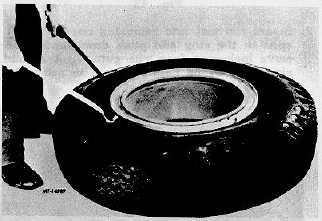
Dismounting:
1.
Deflate tire or both tires if working on duals completely
by removing the valve core, before removing tire and
rim assembly from truck. Remove tire from truck and
place on floor with the side-ring up. Pry bead loose
from side-ring by inserting curved end of rim tool and
hooked-end of rim tool between side-ring and side-wall
of tire. Then apply downward pressure on rim tools.
Continue to pry around tire until bead is completely free
from side-ring (Fig. 37).
Fig. 37
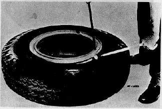
Fig. 38
2.
Insert tapered end of tool into notch on sidering, pry
ring upward and outward to remove side-ring from its
groove in rim. Place hooked-end of tool between the
ring
and tire. Pry upward on ring and downward on tire to free ring
from tire bead (Fig. 38).
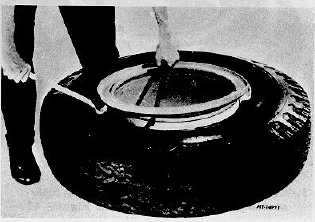
3.
Continue prying around tire until ring is free (Fig. 39).
Turn tire and rim assembly over on floor. Unseat
second bead from rim. Lift the rim from tire. Remove
tube and flap, if used, from tire.
Fig. 39
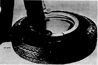
Mounting:
1.
Place tube and flap into tire and partially inflate to
round out tube. Apply approved rubber lubrication to
inside and outside surfaces of both beads and also to
the portion of tube and flap that appears between
beads. With valve slot up place rim flat on floor. Align
valve with rim valve slot, place tire on rim and insert
valve through valve slot. Place side-ring on rim base
with ring split opposite the valve stem. Install leading
end of ring into gutter of rim (Fig. 40).
Fig. 40
CTS-2032N Page 13
PRINTED IN UNITED STATES OF AME RICA
|