|
| |
TRUCK SERVICE MANUAL
TM 5-4210-230-14&P-1
WHEELS, RIMS, TIRES
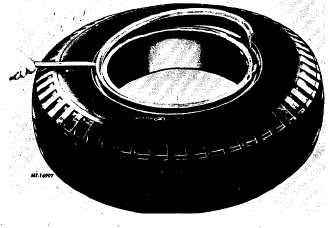
Fig. 45
Mounting'
1.
Insert tube and flap into tire and partially inflate to
round out tube. Apply approved rubber lubricant to
inside and outside surfaces of both beads and also to
the portion of tube and flap that appears between
beads. Lay rim flat on floor with valve slot up. Align
valve with rim valve, place tire on rim and insert valve
through valve slot.
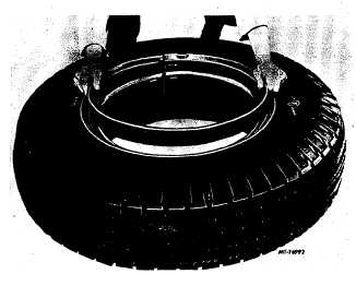
2.
Place side-ring on bead of tire. Insert tapered end of
lock-ring between side-ring and rim base (Fig. 46).
Fig. 46
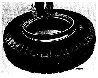
3.
Fasten lock-ring by holding at one end of split with foot
and hammering end of ring into place with rim mallet
,(Fig. 47).
Fig. 47
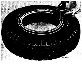
4.
Continue hammering around rim while holding ring with
foot until entire ring is seated (Fig. 48).
Fig. 48
5.
Place tire assembly into safety cage and inflate to a
maximum of 10 psi using extension hose with gauge
and clip-on chuck. Inspect beads, side-ring and lock-
ring for proper seating. Completely deflate tire to
prevent tube from buckling. Reinflate to recommended
pressure.
CTS-2032N Page 15
PRINTED IN UNITED STATES OF AMERICA
|